Method and system of remote diagnostic, control and information collection using a dynamic linked library of multiple formats and multiple protocols with intelligent protocol processor

a technology of intelligent protocol processor and library, applied in the field of remote diagnostic, control and information collection using a dynamic linked library of multiple formats and multiple protocols with intelligent protocol processor, can solve problems such as error conditions and warning conditions, and achieve the effects of facilitating communication system configuration and received data analysis, facilitating the analysis of received data, and efficiently communicating the information of monitored events

Active Publication Date: 2005-01-20
RICOH KK
View PDF12 Cites 25 Cited by
  • Summary
  • Abstract
  • Description
  • Claims
  • Application Information

AI Technical Summary

Benefits of technology

[0010] One object of the present invention is to provide a novel and effective system for monitoring events of a target application of an application unit.
[0012] A further object of the present invention is to provide a system for communicating data obtained by monitoring events of a target application of an application unit to a remote party allowing various data formats and communication protocols to facilitate the communication system configuration and received data analysis.
[0013] A further object of the present invention is to provide a system for communicating data obtained by monitoring events of a target application of an application unit to a remote party allowing various data formats that ease the analyses of received data at the receiving side.
[0014] A further object of the present invention is to efficiently communicate the monitored event information to a transmission unit.
[0015] A further object of the present invention is to efficiently verify the combination of the two parameters specifying the format and protocol and to meet the restriction requirement on the second parameter.
[0016] The present invention achieves these and other objects by monitoring the events of a target application of an application unit. Monitoring examples include (1) monitoring a software program being executed on a computer or workstation under control of a user, (2) monitoring usage of a control panel of an image forming apparatus (e.g., a copying machine, printer, facsimile, or scanner), an appliance (e.g., a microwave oven, VCR, digital camera, cellular phone, or palm top computer), (3) monitoring any internal state changes such as error conditions and warning conditions within appliances, devices and any systems and sending the results when requested or when events occur or when preset time interval occurs, (4) externally monitoring states of appliances, devices or system by polling at regular interval, and (5) generally monitoring any other device or service. The data obtained by monitoring events of a target application of an application unit, appliance, or device can, as a further feature in the present invention, be collected, logged and communicated to a desired location by a store-and-forward protocol (e.g., Internet e-mail) or a “direct” connection protocol in which a socket connection is made to an ultimate destination machine (e.g., using FTP or HTTP). The use of store-and-forward communication reduces the costs associated with communicating such data. The data can be communicated to the desired location at several instances. Such instances include each time a user exits a target application, or after a predetermined number of times that a user has utilized and exited the target application of the application unit. If the configuration allows and if necessary, the direct connection between the monitored application and the monitoring system can be established in addition to the store-and-forward communication.

Problems solved by technology

Some events may be caused by abnormal conditions such as paper jam in the copiers.
Some error conditions and warning conditions may be caused by errors in the software installed in the target appliances and devices.

Method used


Image

  • Method and system of remote diagnostic, control and information collection using a dynamic linked library of multiple formats and multiple protocols with intelligent protocol processor
  • Method and system of remote diagnostic, control and information collection using a dynamic linked library of multiple formats and multiple protocols with intelligent protocol processor
  • Method and system of remote diagnostic, control and information collection using a dynamic linked library of multiple formats and multiple protocols with intelligent protocol processor

Examples


Embodiment Construction

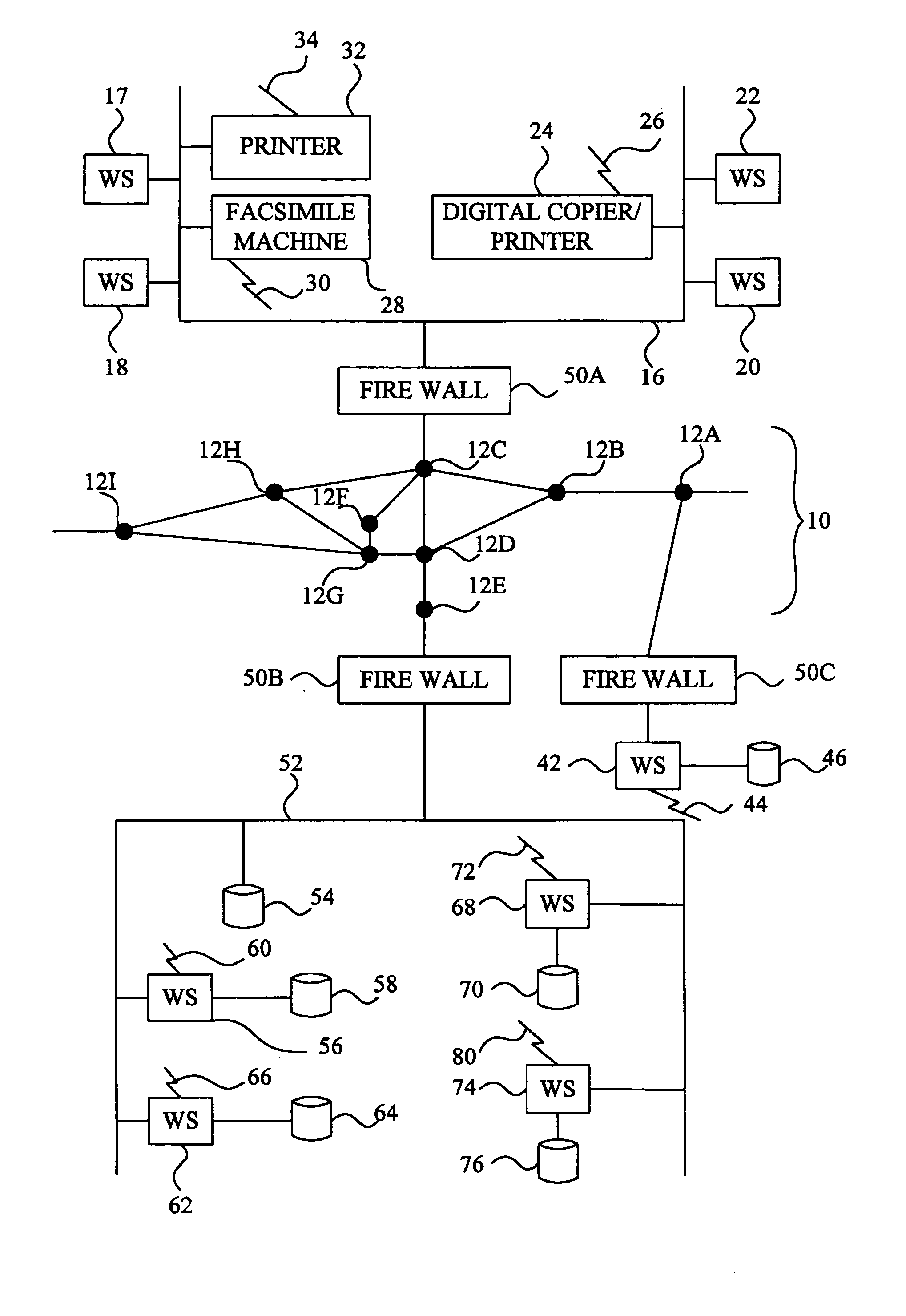
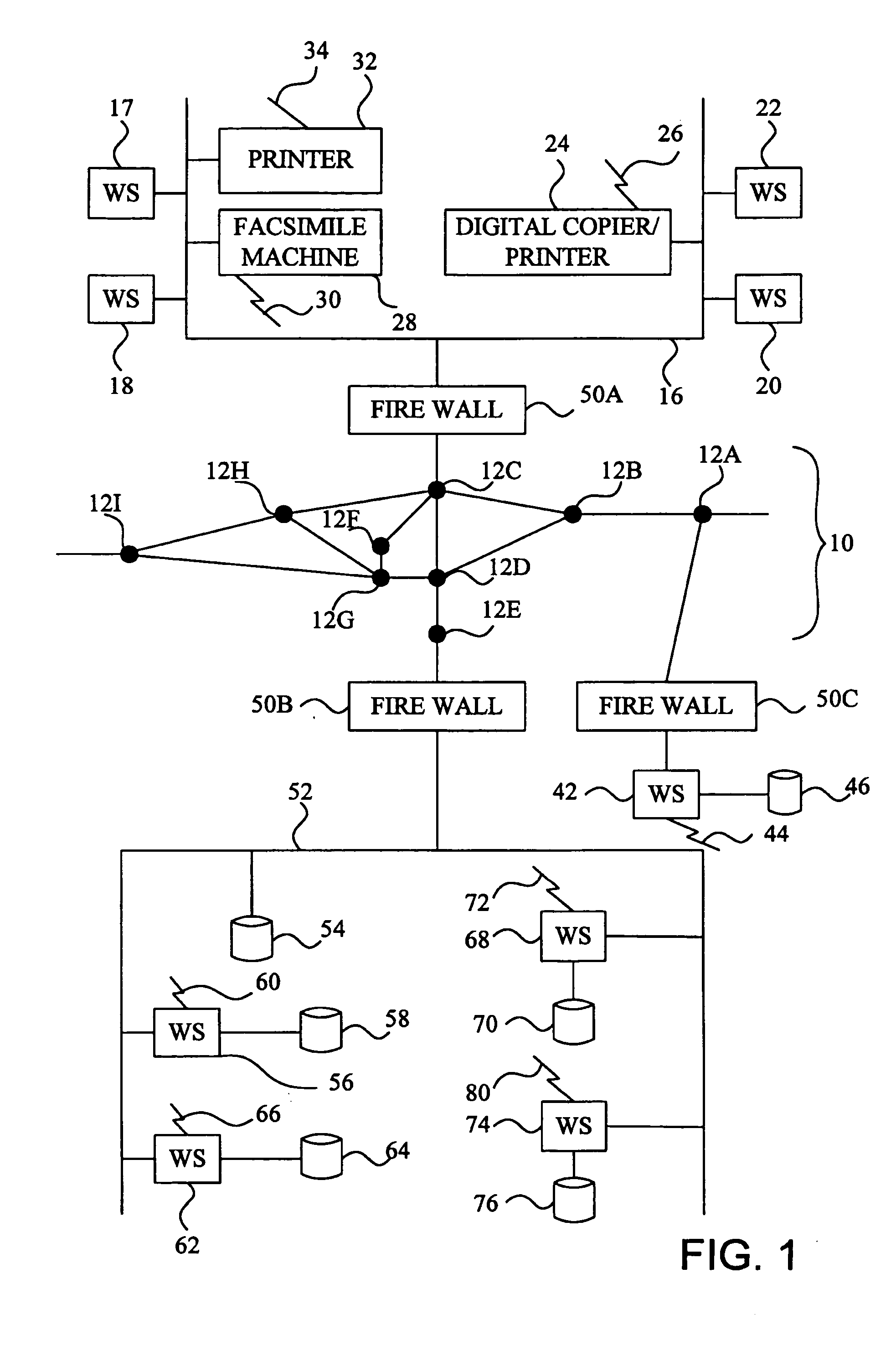
[0048] Referring now to the drawings, wherein like reference numerals designate identical or corresponding parts throughout the several views, FIG. 1 illustrates (1) various machines and (2) computers for monitoring, diagnosing and controlling the operation of the machines. In FIG. 1, there is a first network 16, such as a Local Area Network (LAN) connected to computer workstations 17, 18, 20 and 22. The workstations can be any type of computers including IBM Personal Computer compatible devices, Unix-based computers, or Apple Macintoshes. Also connected to the network 16 are (1) a digital image forming apparatus 24, (2) a facsimile machine 28, and (3) a printer 32. As would be appreciated by one of ordinary skill in the art, two or more of the components of the digital image forming apparatus 24 and the facsimile machine 28 can be combined into a unified “image forming apparatus.” The devices 24, 28 and 32 and the workstations 17, 18, 20 and 22 are referred to as machines or monito...


PUM


Abstract

A method, system and computer program product for (1) collecting information from a remote application unit and / or (2) diagnosing or controlling the remote application unit. By supporting dynamic generation of multiple data formats and / or multiple communication protocols, a computer code device increases the likelihood that a supported format and / or protocol will be either receivable or understandable by a receiver without having to pre-generate the protocol or format processor. By utilizing a shareable computer code device (e.g., a dynamic linked library), a new application can utilize tested, proven code without having to reproduce existing functionality.

Description

CROSS-REFERENCE TO RELATED APPLICATIONS [0001] The present application is a continuation of application Ser. No. 09 / 453,935, filed May 17, 2000. The present application is related to the following U.S. applications and patents: Ser. No. 09 / 453,934 filed 2000 May 17; Ser. No. 09 / 453,936 filed 2000 May 17; Ser. No. 09 / 453,937 filed 2000 May 17; Ser. No. 09 / 440,692 filed 1999 Nov. 16; Ser. No. 09 / 440,647 filed 1999 Nov. 16, now U.S. Pat. No. 6,662,225; Ser. No. 09 / 440,646 filed 1999 Nov. 16; Ser. No. 09 / 440,693 filed 1999 Nov. 16; Ser. No. 09 / 440,645 filed 1999 Nov. 16; Ser. No. 09 / 408,443 filed 1999 Sep. 29, now U.S. Pat. No. 6,631,247; Ser. No. 09 / 407,769 filed 1999 Sep. 29, now U.S. Pat. No. 6,581,092; Ser. No. 09 / 393,677 filed 1999 Sep. 10; Ser. No. 09 / 311,148 filed 1999 May 13; Ser. No. 09 / 192,583 filed 1998 Nov. 17; Ser. No. 09 / 190,460 filed 1998 Nov. 13, now U.S. Pat. No. 6,208,956; Ser. No. 08 / 883,492 filed 1997 Jun. 26; Ser. No. 09 / 108,705 filed 1998 Jul. 1; Ser. No. 09 / 107,98...

Claims


Application Information

Patent Timeline
Patent Type & Authority Applications(United States)
IPC IPC(8): G06F15/173H04L12/24H04L12/26H04L12/58H04L29/06H04L29/08
CPCH04L12/58H04L41/06H04L69/18H04L67/025H04L67/125H04L41/0681H04L51/00
Inventor MOTOYAMA, TETSUROFONG, AVERY
Owner RICOH KK
Why Eureka
Try Eureka