[0013] In either arrangement, the motion sensor(s) may be positioned such that an axis of sensitivity of the sensor is aligned with a
principal direction of movement of the microphone diaphragm. Such a
principal direction of movement may be substantially normal to a surface (e.g., a planar surface) defined by the diaphragm. Such alignment of the motion sensor may allow for enhanced detection of undesired movement between the diaphragm and overlying tissue (e.g., skin). More preferably, such an axis of sensitivity may extend through the
center of mass of the microphone. This may allow for more accurately identifying movement of the microphone as an
assembly. Accordingly, the
center of mass of the microphone
assembly and motion sensor(s) may be located on a common axis that may also be directed normal to the
principal direction of movement of the microphone diaphragm. In an arrangement where a plurality of motion sensor(s) are employed, the sensors may be positioned so that their
centroid or combinative
center of mass is located on such a common axis.
[0014] In another aspect utilizing a motion sensor to yield a microphone output signal that is less vibration sensitive, the output of the motion sensor may be processed with an output of the implantable microphone
transducer to provide an
audio signal that is less vibration-sensitive than the microphone output alone. For example, the motion sensor output may be appropriately scaled,
phase shifted and / or frequency-shaped to match a difference in
frequency response between the motion sensor output and the microphone transducer output, then subtracted from the microphone transducer output to yield a net, improved
audio signal employable for driving a
middle ear transducer, an
inner ear transducer and / or a
cochlear implant stimulation
system.
[0015] In a yet further aspect of the invention, the motion sensor output may be utilized by a controller to provide a control output to at least one
actuator. Such an actuator may be capable of moving an implantable microphone
assembly housing or an
implant capsule (e.g., relative to a vibrational source), so as to substantially reduce movement of the microphone diaphragm relative to the skin of a patient which covers the microphone diaphragm. By way of example only, a piezo-electric, electromagnetic, or acoustic actuator(s) may be employed.
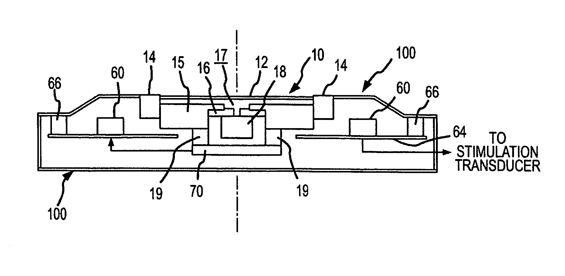
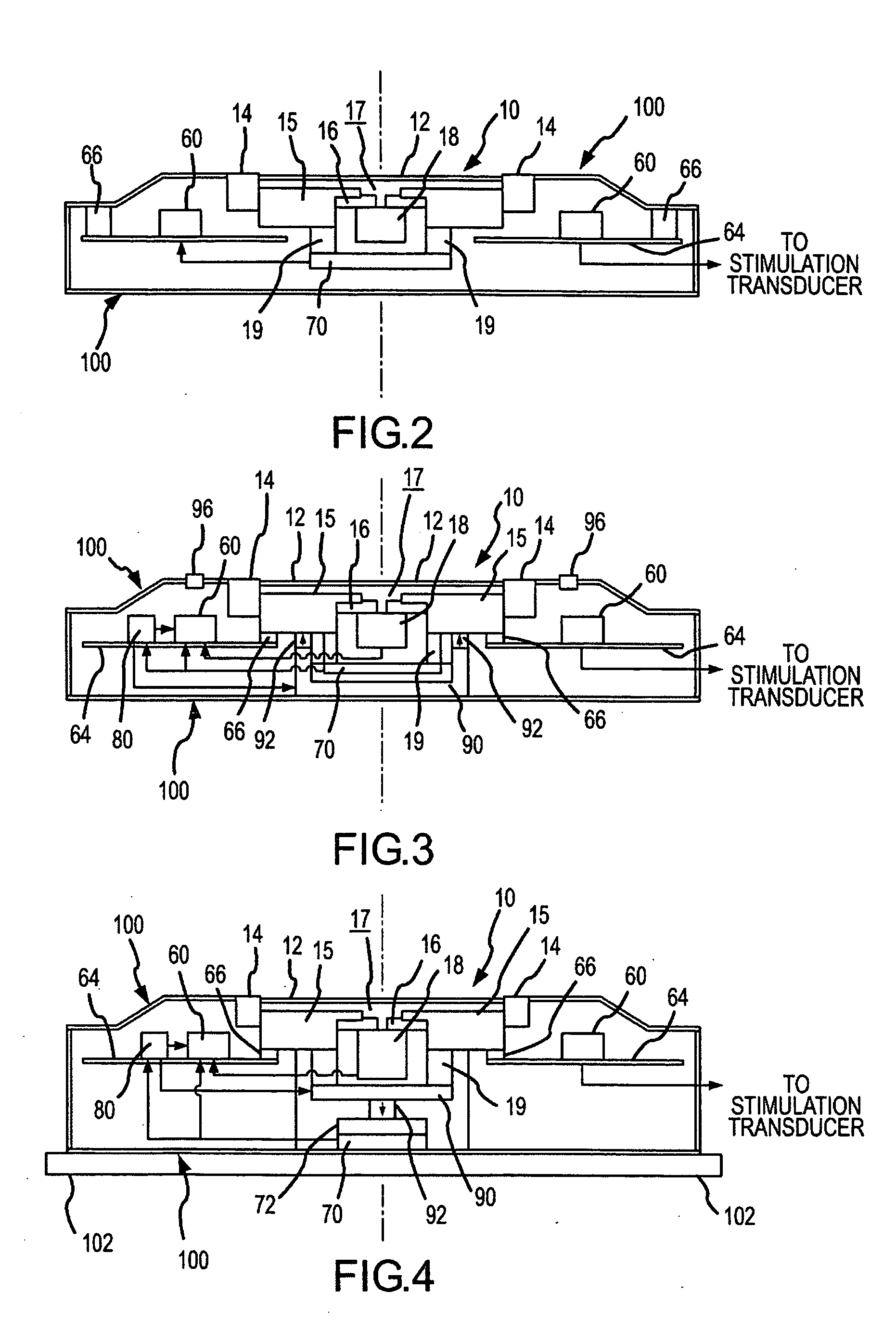
[0016] As noted, in certain arrangements the motion sensor(s) may be interconnected to a part of an implantable microphone for co-movement therewith. In such arrangements, the actuator(s) may be interconnected to an
implant capsule and actuatable to apply forces to the microphone (e.g., the microphone housing) so as to reduce undesired movement of the external diaphragm. In such arrangements, a compliant member may be interposed between the microphone assembly and that portion of the implant capsule to which the actuator(s) is interconnected. As further noted above, in certain arrangements the motion sensor(s) may be interconnected to an implant capsule. In turn the motion sensor(s) may be interconnected to a
proof mass, i.e., a reference
mass for the motion sensor(s). In such arrangements, the actuator(s) may be interconnected to the microphone (e.g., the microphone housing) and actuatable to apply forces against the implant capsule and / or the motion sensor (e.g., a
proof mass of the sensor) to reduce undesired movement of the external diaphragm. Further, a compliant member may be interposed between the implant capsule and a patient's
skull or other anatomical structure upon implantation, allowing forces of the actuator to move the implant capsule relative to the
skull or other anatomical structure.
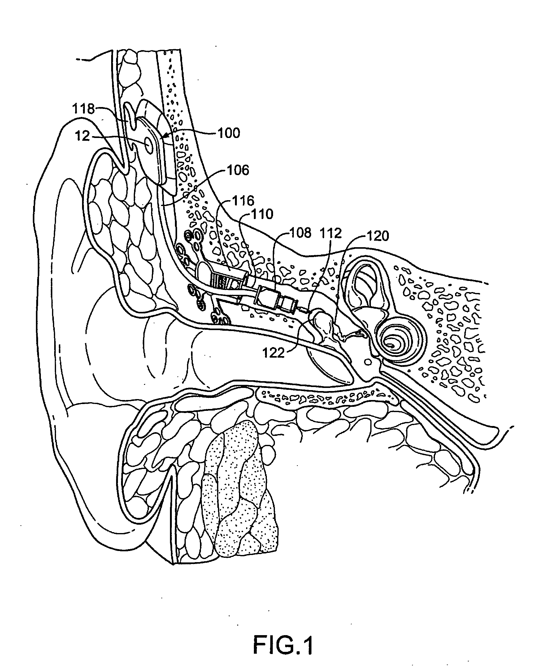
[0018] In a related aspect, a method for attenuating undesired movement of an implantable microphone is provided. The method includes generating a motion signal that is indicative of movement of an implantable support member associated with an implantable microphone diaphragm. Preferably, the implantable support member is substantially isolated from outside sound such that the motion of the member is primarily caused by undesirable sources of vibration. In response to the motion signal, a force is applied at least in part to the support member to reduce relative movement between the microphone diaphragm and tissue overlying the microphone diaphragm. In this regard, the microphone diaphragm may be moved in response to the undesired motion to reduce or attenuate relative movement between the microphone diaphragm and overlying tissue. As will be appreciated, such relative movement may result in the application of forces to the diaphragm, which may be represented as undesired sound (e.g.,
noise). By reducing this relative movement, the output of an implanted microphone may be enhanced for hearing purposes.
[0020] Further, to reduce relative movement, it may be desirable to apply a force aligned with the primary direction of movement of the microphone diaphragm. That is, by moving the microphone diaphragm primarily in the direction that is most likely to result in undesirable sound, more relative movement may be attenuated. Accordingly, more undesirable sound may be removed from an output of the microphone.

