

Optical disk, method for producing the same, and recording and reproducing apparatus
a technology of optical disks and optical disks, which is applied in the direction of optical recording/reproducing/erasing methods, recording information storage, instruments, etc., can solve the problems of inability to accurately reproduce not only the control data but also the information concerning the type of optical disks, and achieve the effect of fast and highly reliable reproduction
- Summary
- Abstract
- Description
- Claims
- Application Information
AI Technical Summary
Benefits of technology
Problems solved by technology
Method used
Image

Examples
first embodiment
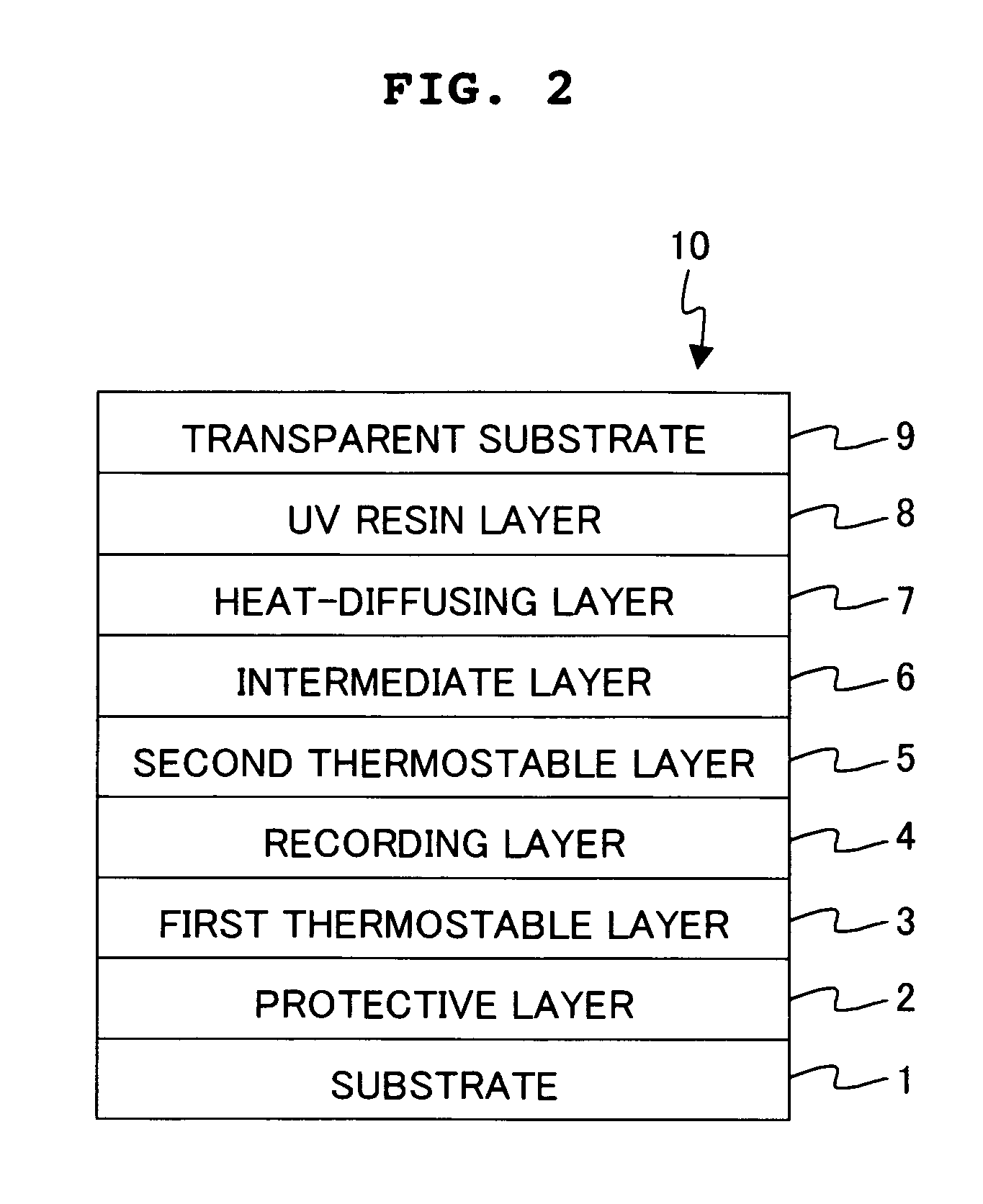
Structure of Optical Disk
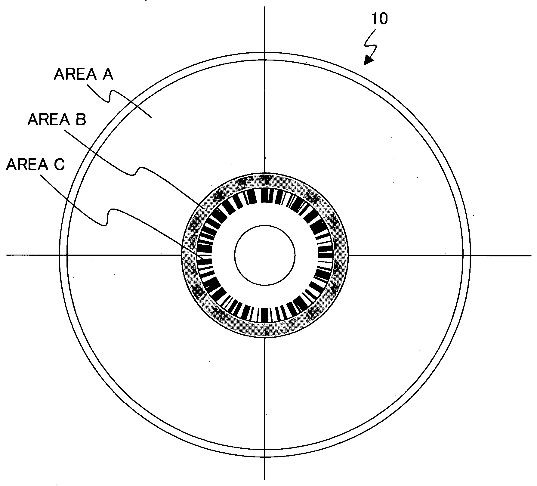
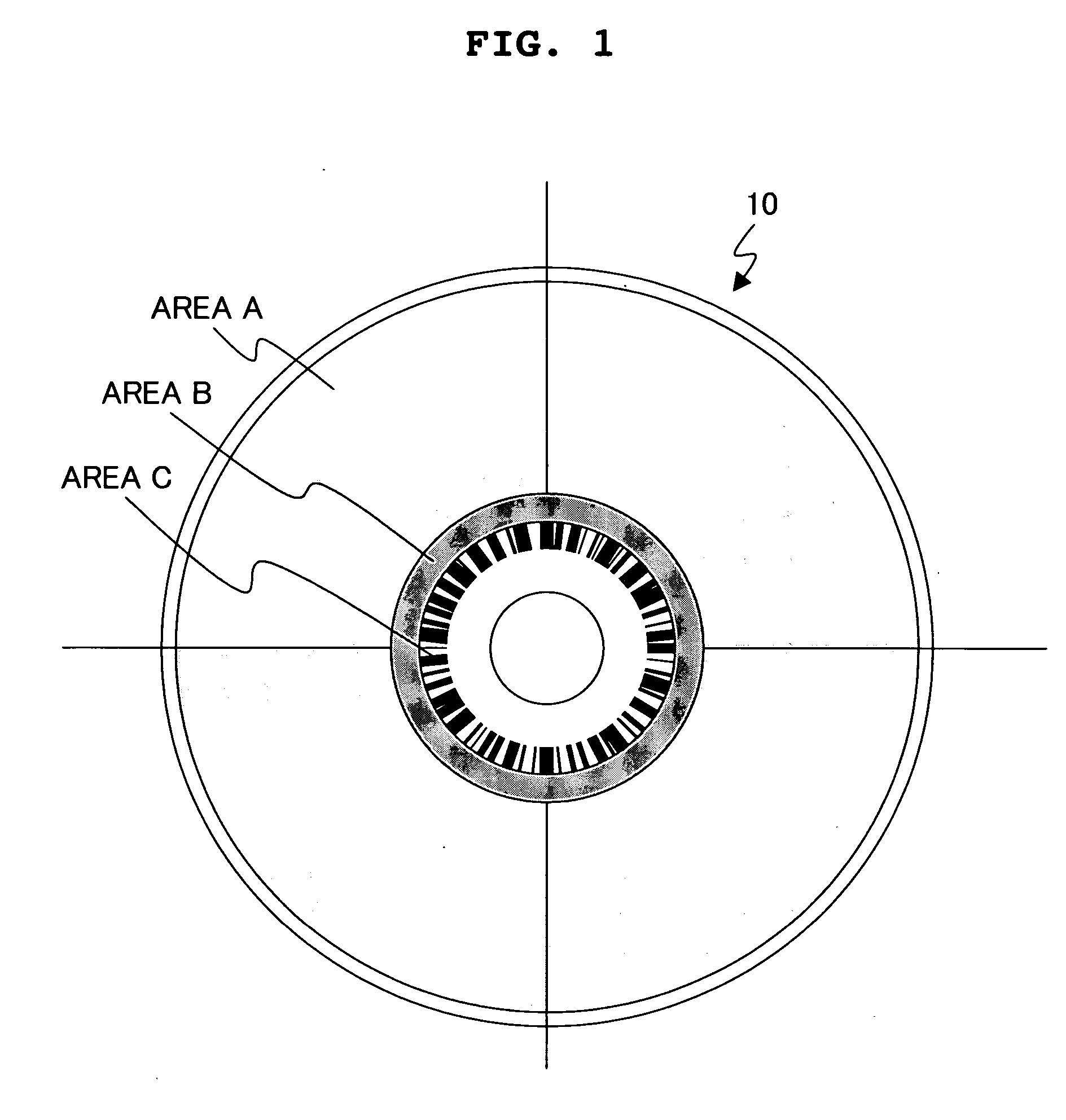
[0074] An HL disk based on the phase-change recording system was manufactured as the optical disk in a first embodiment. FIG. 1 shows a schematic plan view illustrating the optical disk manufactured in this embodiment. As shown in FIG. 1, those successively provided from the outer circumferential side on the optical disk 10 of this embodiment include a user data area A in which user data is recorded, a control data area B in which physical format information about the optical disk 10 is recorded, and a bar code area C in which information is recorded with a bar code-shaped mark group (also referred to as “bar code information”) including a plurality of marks extending in the radial directions and arranged in the track direction.
[0075] The user data area A is provided in the area of the optical disk 10 ranging over radii from about 23.8 mm to 58.5 mm. A groove having a depth of 45 nm is formed in a spiral form at a track pitch of 0.68 μm in the user data a...
second embodiment
[0088] In a second embodiment, an LH disk based on the phase-change recording system was manufactured as the optical disk. The optical disk manufactured in this embodiment had the same schematic plan view as that shown in FIG. 1. Those recorded in the bar code area C include not only the optical disk identification information such as media ID and version information but also the information which indicates the relationship between the reflectance in the non-recorded state and the reflectance in the recorded state in the user data area A of the optical disk. Specifically, the optical disk manufactured in this embodiment is an LH disk. Therefore, the information, which indicates the increase in the reflectance in accordance with the recording, was recorded at a predetermined position in the bar code area C. Values of the reflectance in the non-recorded state and the reflectance in the recorded state in the user data area A may be recorded as the information about the reflectance of t...
third embodiment
Structure of Optical Disk
[0098] An HL disk having the organic dye recording film was manufactured as the optical disk in a third embodiment. The optical disk manufactured in this embodiment has the same schematic plan view as those of the first and second embodiments. As shown in FIG. 1, those successively provided from the outer circumferential side include a user data area A in which user data is recorded, a control data area B in which physical format information about the optical disk is recorded, and a bar code area C in which information is recorded with a bar code-shaped mark group (also referred to as “bar code information”) including a plurality of marks extending in the radial directions and arranged in the track direction.
[0099] The user data area A is provided in the area of the optical disk ranging over radii from about 23.8 mm to 58.5 mm. A groove having a depth of 80 nm is formed in a spiral form at a track pitch of 0.4 μm in the user data area A. A header recordin...
PUM
| Property | Measurement | Unit |
|---|---|---|
| length | aaaaa | aaaaa |
| crystallization temperature | aaaaa | aaaaa |
| radii | aaaaa | aaaaa |
Abstract
Description
Claims
Application Information