
Optical disk with a plurality of radially extending marks for recording reflectance data of the optical disk

a technology of optical disks and reflectance data, applied in the field of optical disks, can solve the problems of inability to accurately reproduce information from both the hl disk and the lh disk by using any identical recording and reproducing apparatus, and the adjustment of the type of the optical disk requires a long period of time, so as to achieve rapid and highly reliable reproduction

Active Publication Date: 2009-03-17
MAXELL HLDG LTD
View PDF28 Cites 3 Cited by
  • Summary
  • Abstract
  • Description
  • Claims
  • Application Information

AI Technical Summary

Benefits of technology

The present invention provides an optical disk and a recording and reproducing apparatus that can quickly and reliably reproduce information even when the optical disk is either a HL disk or a LH disk. The optical disk includes a first area on which user information is recorded and a second area in which a plurality of marks radially extending are arranged. Information about the reflectance of the optical disk is recorded in the second area. The second area is also referred to as the bar code area. The bar code area is formed to have a sufficient length in the radial directions to easily reproduce the information even when the position of the light beam is not strictly controlled. The information recorded in the bar code area is information about the reflectance in the non-recorded state and the recorded state. The optical disk also includes a concentric or spiral guide groove in the first area, and address information is recorded by deflecting the guide groove in the radial direction of the optical disk. The user information is recorded on at least one of the guide groove and an area between the guide grooves. The track pitch of the first area is narrowed to realize a large capacity of information. The invention solves the problem of cross erase or crosstalk that occurs when recording marks are recorded on an extremely narrow track.

Problems solved by technology

When each of the optical disks is installed to a conventional recording and reproducing apparatus to record and reproduce information, the following problems arise due to the difference in the film structure.
Therefore, a problem arises such that it is impossible to reproduce information stably and highly reliably from both of the HL disk and the LH disk by using any identical recording and reproducing apparatus.
Therefore, if the gain is not adjusted, it is impossible to accurately reproduce not only the control data but also the information concerning the type of the optical disk.
Therefore, a problem arises such that the gain adjustment requires a long period of time, and it is impossible to quickly reproduce the control data and the user data.
However, at present, there is no method for solving this problem.
It is also impossible to find any method for optimizing the gain depending on the type of the optical disk (HL disk or LH disk).

Method used


Image

  • Optical disk with a plurality of radially extending marks for recording reflectance data of the optical disk
  • Optical disk with a plurality of radially extending marks for recording reflectance data of the optical disk
  • Optical disk with a plurality of radially extending marks for recording reflectance data of the optical disk

Examples


first embodiment

Structure of Optical Disk

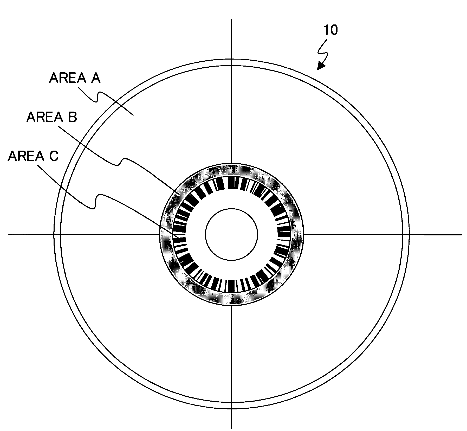
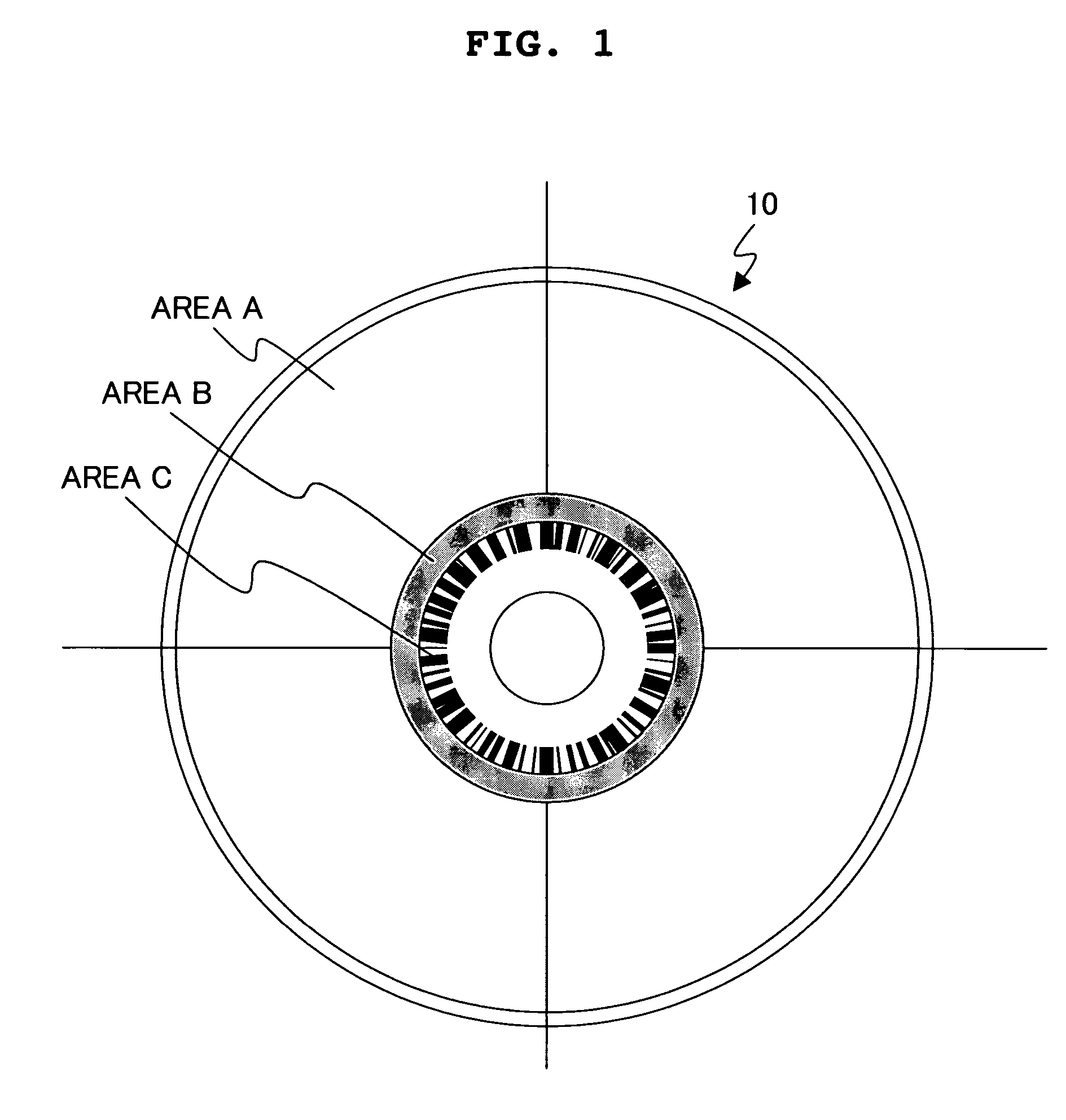
[0074]An HL disk based on the phase-change recording system was manufactured as the optical disk in a first embodiment. FIG. 1 shows a schematic plan view illustrating the optical disk manufactured in this embodiment. As shown in FIG. 1, those successively provided from the outer circumferential side on the optical disk 10 of this embodiment include a user data area A in which user data is recorded, a control data area B in which physical format information about the optical disk 10 is recorded, and a bar code area C in which information is recorded with a bar code-shaped mark group (also referred to as “bar code information”) including a plurality of marks extending in the radial directions and arranged in the track direction.

[0075]The user data area A is provided in the area of the optical disk 10 ranging over radii from about 23.8 mm to 58.5 mm. A groove having a depth of 45 nm is formed in a spiral form at a track pitch of 0.68 μm in the user data area A...

second embodiment

[0088]In a second embodiment, an LH disk based on the phase-change recording system was manufactured as the optical disk. The optical disk manufactured in this embodiment had the same schematic plan view as that shown in FIG. 1. Those recorded in the bar code area C include not only the optical disk identification information such as media ID and version information but also the information which indicates the relationship between the reflectance in the non-recorded state and the reflectance in the recorded state in the user data area A of the optical disk. Specifically, the optical disk manufactured in this embodiment is an LH disk. Therefore, the information, which indicates the increase in the reflectance in accordance with the recording, was recorded at a predetermined position in the bar code area C. Values of the reflectance in the non-recorded state and the reflectance in the recorded state in the user data area A may be recorded as the information about the reflectance of th...

third embodiment

Structure of Optical Disk

[0098]An HL disk having the organic dye recording film was manufactured as the optical disk in a third embodiment. The optical disk manufactured in this embodiment has the same schematic plan view as those of the first and second embodiments. As shown in FIG. 1, those successively provided from the outer circumferential side include a user data area A in which user data is recorded, a control data area B in which physical format information about the optical disk is recorded, and a bar code area C in which information is recorded with a bar code-shaped mark group (also referred to as “bar code information”) including a plurality of marks extending in the radial directions and arranged in the track direction.

[0099]The user data area A is provided in the area of the optical disk ranging over radii from about 23.8 mm to 58.5 mm. A groove having a depth of 80 nm is formed in a spiral form at a track pitch of 0.4 μm in the user data area A. A header recording sec...


PUM

PropertyMeasurementUnit
lengthaaaaaaaaaa
crystallization temperatureaaaaaaaaaa
radiiaaaaaaaaaa

Abstract

An optical disk includes a first area on which user information is recorded, and a second area in which a plurality of marks radially extending are arranged in a track direction in the optical disk. Information about the reflectance of the optical disk is recorded in the second area. It is intended to optimize the amplification factor of the reproduced signal on the basis of the information about the reflectance of the optical disk in the second area. Control data and user data can be reproduced quickly and highly reliably without depending on the relationship between the reflectances of a recording area and a non-recorded area of the optical disk.

Description

BACKGROUND OF THE INVENTION[0001]1. Field of the Invention[0002]The present invention relates to an optical disk, a method for producing the same, and a recording and reproducing apparatus. In particular, the present invention relates to an optical disk which stably reproduces information recorded on optical disks having different reflectances, a method for producing the same, and a recording and reproducing apparatus.[0003]2. Description of the Related Art[0004]DVD, which has appeared in recent years, has a lineup including, for example, not only information read-only DVD-ROM and DVD-Video but also information recordable DVD-R and information rewritable DVD-RAM and DVD-RW. Therefore, the DVD market is rapidly expanded not only as the screen image-recording and reproducing medium which substitutes VTR but also as the large capacity medium for computers. Recently, the digital broadcast has come into widespread use, which simultaneously increases the demand for any medium capable of r...

Claims


Application Information

Patent Timeline
Patent Type & Authority Patents(United States)
IPC IPC(8): G11B7/24G11B7/00G11B7/004G11B7/005G11B7/007G11B7/24035G11B7/24079G11B7/24082G11B7/24085G11B7/24097G11B7/243G11B7/244G11B7/26
CPCG11B7/00736G11B7/0053Y10T428/21G11B7/268G11B7/24079
Inventor TAMURA, REIJISHIRAI, HIROSHI
Owner MAXELL HLDG LTD
Learn More