Method for detecting an oscillation in an on-frequency repeater

a technology of on-frequency repeaters and oscillation detection, which is applied in the direction of repeater/relay circuits, frequency-division multiplexes, transmission monitoring, etc., can solve the problems of system oscillation, on-frequency repeaters, and serious degrade the quality of desired rf signals

Inactive Publication Date: 2005-06-02
SPOTWAVE WIRELESS INC
View PDF9 Cites 105 Cited by
  • Summary
  • Abstract
  • Description
  • Claims
  • Application Information

AI Technical Summary

Benefits of technology

[0019] Accordingly, an object of the present invention is to provide low-cost methods and systems for detecting and controlling oscillation of an on-frequency repeater.

Problems solved by technology

For example, within a building, or a built-up urban area, signal attenuation, shadowing by buildings and / or hills; noise generated by various radio frequency sources, and multi-path effects can seriously degrade the quality of desired RF signals.
This delay is partly inherent to the amplification process, but it is primarily caused by band-pass filters used in the repeater to prevent the unwanted amplification of signals outside the frequency band of interest.
A limitation of on-frequency repeaters is that the output signal (So) can feed back to the repeater input via a so-called “leakage path”.
However, if the system gain (G) becomes too high, so that Sf≧Se, then signal leakage between the output and input antennas will cause system oscillation.
However, in practice, antenna isolation is difficult to predict, and will frequently change over time.
This margin significantly decreases the effectiveness of the repeater and yet does not prevent oscillation for all potential RF environments.
This system is designed to handle a single communication signal with narrowband analog voice modulation, and thus is not suitable for use with broadband signal traffic carrying multiple parallel communication signals.
However, it suffers the limitation that the tag must be located in a side-band (i.e., lying above or below the bandwidth of the desired communications signal traffic) in order to avoid interference corrupting the desired communications signal traffic and / or interfering with other network components.
This necessarily requires interruption of the communications signal traffic, which is highly undesirable.
The systems of U.S. Pat. Nos. 4,383,331 and 5,835,848 suffer the further disadvantage that, in most cases, the power level of the received test (pilot or tag) signal will be very low, requiring highly sensitive detection circuitry to successfully monitor.
However, this high sensitivity renders the detection circuit vulnerable to radio frequency interference (RFI) emitted by many common electronic devices and / or test signals transmitted by other repeaters.
The presence of noise at the same frequency as the test signal can easily render the system incapable of accurately detecting antenna isolation, and in fact may disable the repeater entirely.
However, accurate correlation between the received signal and the bit-sequence is computationally intensive.
Another limitation of repeaters is that the repeater is always “on”.
In the uplink path, this means that random RFI within the coverage area is amplified and radiated toward the base station, which increases the noise environment of the base station.

Method used


Image

  • Method for detecting an oscillation in an on-frequency repeater
  • Method for detecting an oscillation in an on-frequency repeater
  • Method for detecting an oscillation in an on-frequency repeater

Examples


Embodiment Construction

[0029] The following description utilizes exemplary power levels, power ranges, channel frequencies and band-widths in order to illustrate various features of the present invention. Those skilled in the art will appreciate, however, that the present invention is by no means limited to such values. On the contrary, those skilled in the art will readily understand that the present invention can be deployed for use in conjunction with any wireless communications network, and it is to be expected that the power levels, power ranges, channel frequencies, and band-widths stated herein will be modified to conform to the requirements of the communications network in question. Such modifications are considered to be well within the purview of those of ordinary skill in the art, and lie within the intended scope of the appended claims.

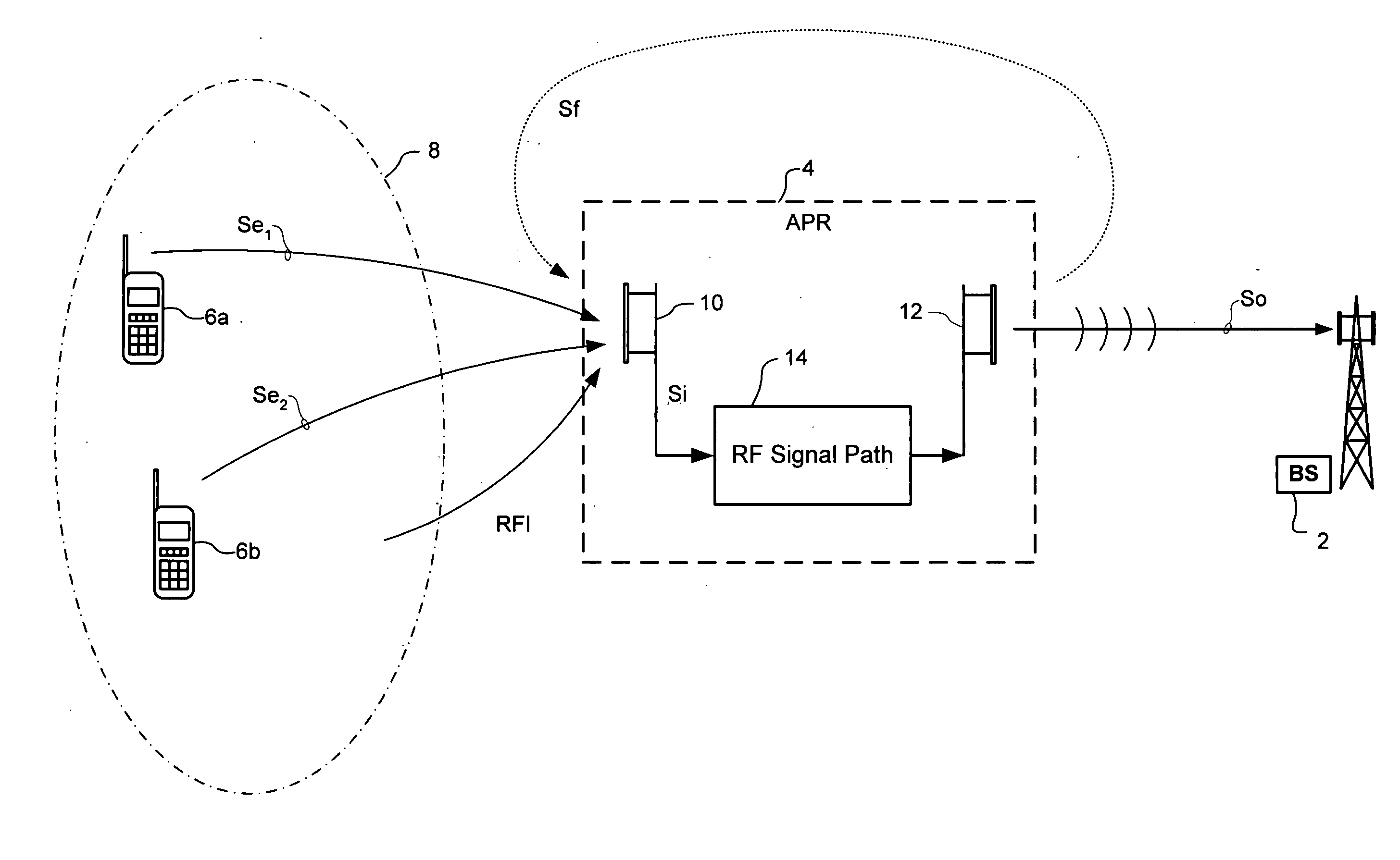
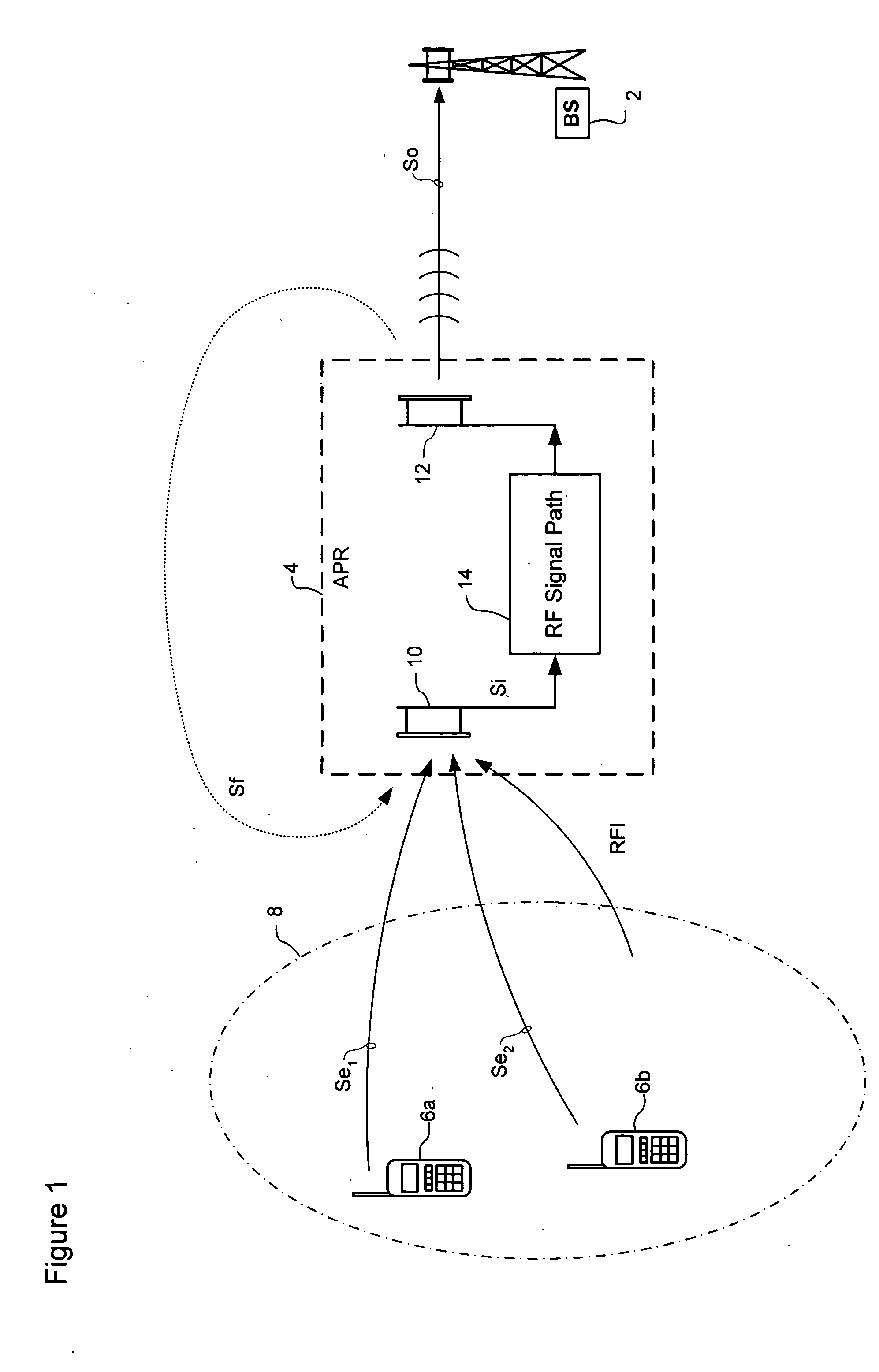
[0030] The present invention provides a system and method for detecting oscillation in an on-frequency repeater. FIG. 1 is a block diagram schematically illust...


PUM


Abstract

A method of detecting oscillation in an on-frequency repeater having an RF signal path coupled between an input antenna and an output antenna. In accordance with the present invention, a first RF signal power level within the RF signal path is detected during an un-muted period in which transmission of an output RF signal through the output antenna is enabled. A second RF signal power level within the RF signal path is detected during a mute period in which transmission of an RF signal through the output antenna is disabled. The first and second detected RF signal power levels are then compared, which provides an indication of signal leakage, and thus oscillation.

Description

CROSS-REFERENCE TO RELATED APPLICATIONS [0001] This is application is a continuation in part of U.S. Patent Application No. 60 / 502,949 filed on Sep. 16, 2003.BACKGROUND OF THE INVENTION [0002] The use of wireless repeaters to extend the coverage area of a wireless network, or to improve service quality within specific areas, are well known. A typical application of repeaters is for improving wireless services within defined regions of a wireless network, where signal levels would otherwise be too low for satisfactory quality of service. For example, within a building, or a built-up urban area, signal attenuation, shadowing by buildings and / or hills; noise generated by various radio frequency sources, and multi-path effects can seriously degrade the quality of desired RF signals. In some cases, a wireless network provider may install a repeater in order to improve service in a region lying at an edge of the coverage area serviced by a base station, thereby effectively extending the r...

Claims


Application Information

Patent Timeline
Patent Type & Authority Applications(United States)
IPC IPC(8): H04B7/15
CPCH04B7/15578
Inventor ALLEN, STEVECOLLEDAN, MARC
Owner SPOTWAVE WIRELESS INC
Why Eureka
Try Eureka