Impeller adjustment device and method for doing the same for close coupled pumps

Active Publication Date: 2005-08-04
ITT MFG ENTERPRISES LLC
View PDF11 Cites 9 Cited by
  • Summary
  • Abstract
  • Description
  • Claims
  • Application Information

AI Technical Summary

Benefits of technology

[0007] One advantage of the invention is that it allows impeller adjustment externally while the unit is fully assembled. Tolerance can be renewed at any time to maintain optimum unit performa

Problems solved by technology

However, current devices are difficult to set accurately and reside in the process fluids where they are susceptible to corrosion/erosion.
Due to this complicated process, many times impeller clearances are simply set “close” and hereby cause the pumps to operate

Method used


Image

  • Impeller adjustment device and method for doing the same for close coupled pumps
  • Impeller adjustment device and method for doing the same for close coupled pumps
  • Impeller adjustment device and method for doing the same for close coupled pumps

Examples


Example

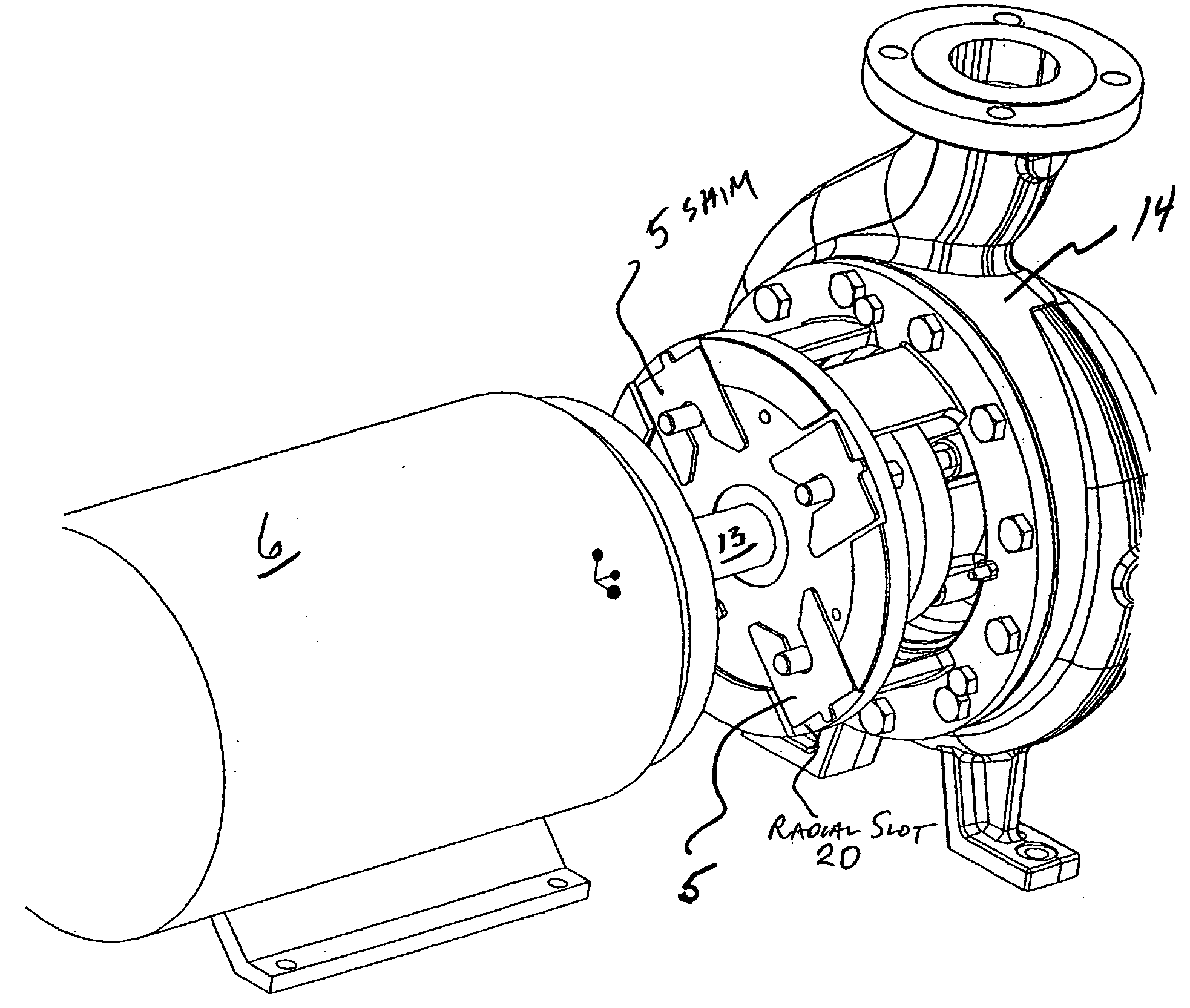
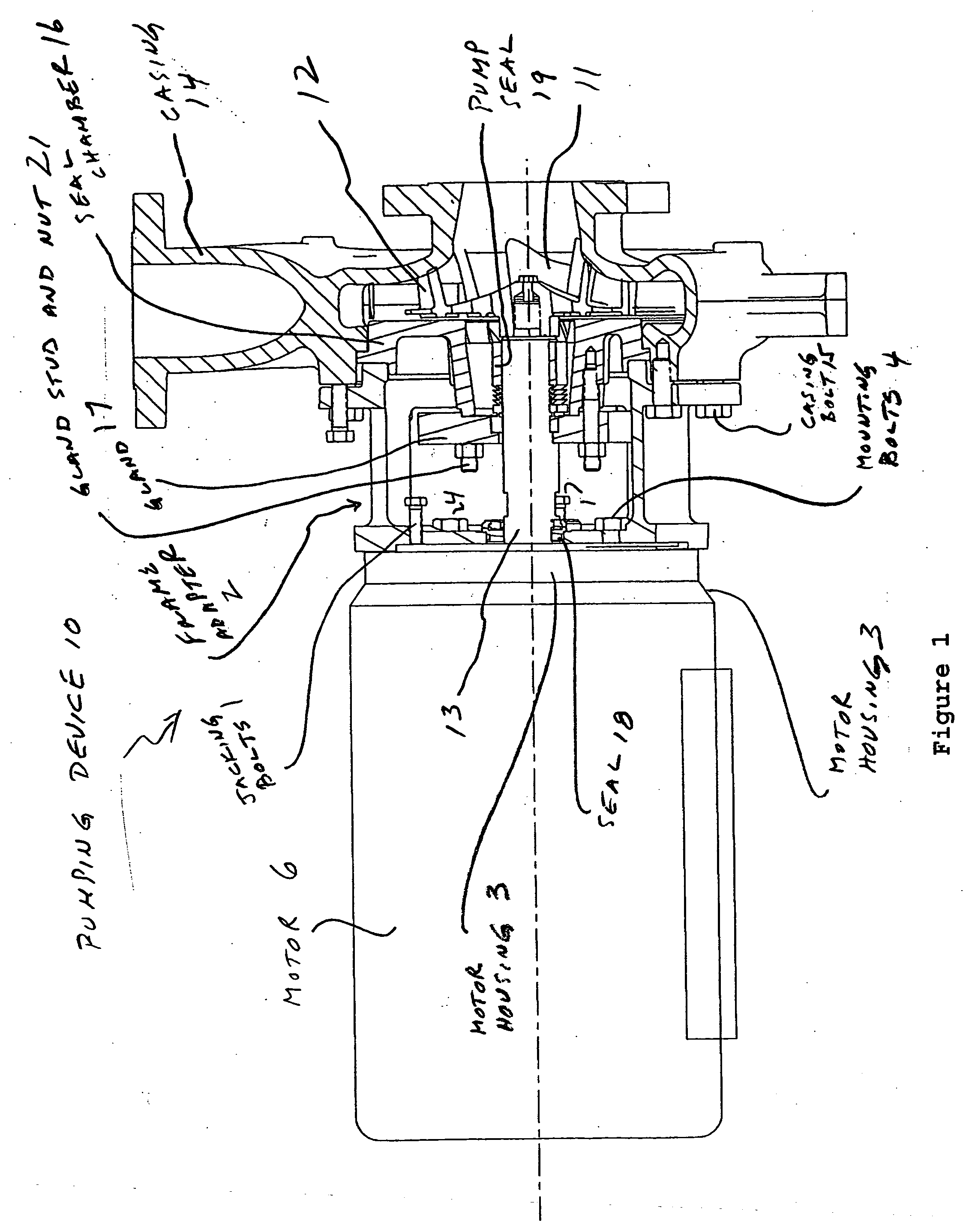
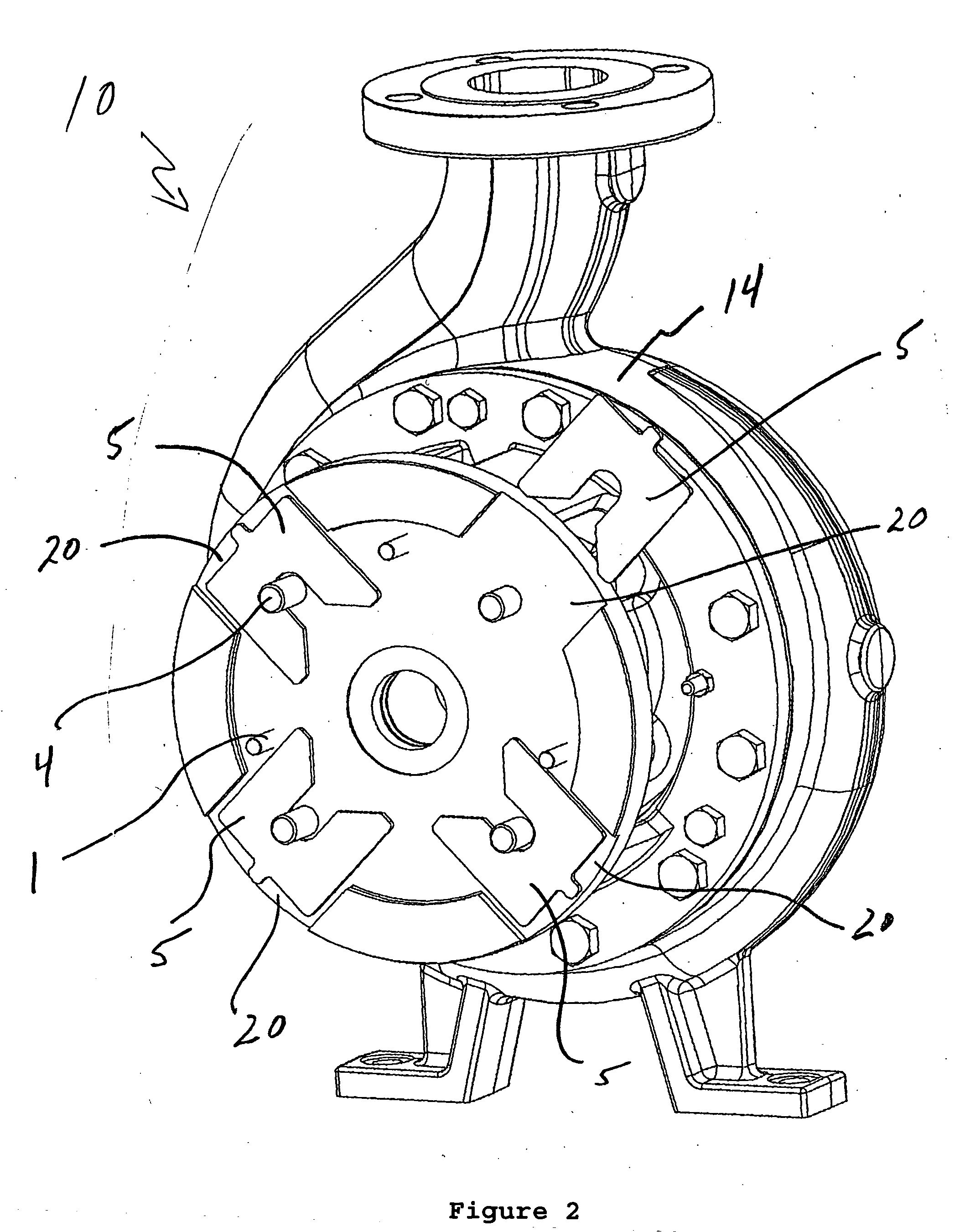
[0013]FIGS. 1-4 show a pumping device 10 having a pump frame adapter 2 for coupling a motor 6 to an impeller assembly 12 having an impeller 11 arranged on an impeller shaft 13. In accordance with the present invention, the impeller 11 is adjusted in the impeller assembly 12, as follows:

[0014] The pumping device 10 has jacking bolts 1 in the rear of the pump frame adapter 2 that push against a motor housing 3 of the motor 6.

[0015] During assembly, the pump frame adapter 2 is mounted to the motor 6 and secured with mounting bolts 4. The mounting bolts 4 should all be tightened until the pump frame adapter 2 is tight against the motor housing3. A seal 18 is pushed on to the impeller shaft 13 and seated into the pump frame adapter 2. The pump seal assembly consisting of a gland 17 and a pump seal 19 are positioned on the impeller shaft 13. A seal chamber 16 is mounted on the pump frame adapter 2 and secured with screws (not shown). The gland 17 is then secured to the seal chamber 16 w...


PUM

PropertyMeasurementUnit
Distanceaaaaaaaaaa

Abstract

A method and apparatus are provided for adjusting an impeller in a motor and impeller assembly of a pumping device. The method features steps of: tightening mounting bolts so as to move the motor and impeller assembly of the pumping device forward until the impeller touches a casing; inserting a feeler gauge in radial slots in a frame adapter and measuring a gap between a housing of the motor and the frame adapter; determining a desired impeller adjustment distance based on the gap and the desired impeller running clearance; selecting at least one shim having a thickness that corresponds to the desired impeller adjustment distance; loosening the mounting bolts and threading jacking bolts arranged in the rear of the pump frame adapter so that the jacking bolts push against the housing of the motor, and the shims can then be inserted into the radial slots; inserting the shims into the radial slots; backing out the jacking bolts; and securing the mounting bolts locking the motor and impeller assembly in position so that the impeller is at the desired impeller adjustment distance in relation to the casing. The frame adapter assembly features a frame adapter having four radial slots to enable access to the gap for measurement with a feeler gauge and for insertion of the shim to accurately set the impeller clearance.

Description

BACKGROUND OF THE INVENTION [0001] 1. Field of Invention [0002] The present invention relates to a method and apparatus for adjusting an impeller coupled to a motor in relation to an impeller assembly; and more particularly relates to a method and apparatus for adjusting such an impeller in a close coupled centrifugal pump. [0003] 2. Description of Related Art [0004] Internal bushings or shims to set impeller clearance for optimum pump performance are known. However, current devices are difficult to set accurately and reside in the process fluids where they are susceptible to corrosion / erosion. Current methods and apparatus require the user to completely assemble the pump, then insert a feeler gauge into the suction (which is often only 1″ diameter) to set the impeller-to-casing clearance. Then the unit must be disassembled and the appropriate bushing or shims added to the shaft behind the impeller hub. The units are then reassembled and the clearances re-checked. Since gasket and / o...

Claims


Application Information

Patent Timeline
IPC IPC(8): F04B17/00F04B35/04F04D29/62
CPCF04D29/628F04D29/622Y10T29/49238Y10T29/49229Y10T29/49236
Inventor BIVER, PAUL J.PLAYFORD, MARK A.QUILL, JEREMIAH D.PECK, GREGORY L.
Owner ITT MFG ENTERPRISES LLC
Why Eureka
Try Eureka