Anal retractor

Inactive Publication Date: 2005-09-15
AGILENT TECH INC +1
View PDF15 Cites 21 Cited by
  • Summary
  • Abstract
  • Description
  • Claims
  • Application Information

AI Technical Summary

Benefits of technology

[0006] The invention is concerned with the task of providing an anal retractor which makes possible an improved access for medical examination and intervention.
[0009] In the inventive anal retractor the retractor valves are guided radially slideable in a base plate. Thereby it becomes possible to provide a greater number of retractor valves symmetrically about a central free opening of the base plate and accordingly it becomes possible to dilate the anal canal symmetrically with optimal cross-section. If three retractor valves are employed, which are offset radially at an angle of 120° relative to each other, then there results a triangular widening of the anal canal. An optimal embodiment is produced using four retractor valves, which are radially displaceable in guides offset by 90° relative to each other. The four retractor valves produce an approximately square access cross-section of the dilated anal canal, which provides the doctor with a greater freedom of movement. More than four retractor valves are possible in accordance with the invention; however, more retractor valves do not provide any substantial improvement in the access cross-section, but lead rather to a greater coverage of the wall of the anal canal by the retractor valves.
[0013] In order to be able to introduce the anal retractor as painless as possible and without tissue damage, a mandrel is preferably provided, which can be seated centrally in the base plate. The mandrel projects distally beyond the base plate and exhibits a distal truncated conical end piece. When the retractor valves are slid to their radial innermost position, the distal free ends of the retractor valves engage behind the proximal edge of the conic end piece, and are covered by the end piece when the mandrel is introduced into the anal canal with the retractor valves lying there-against. As soon as the retractor valves are positioned in the anal canal, these are radially moved apart, so that the mandrel, together with its conical end piece, can be withdrawn proximally.

Problems solved by technology

More than four retractor valves are possible in accordance with the invention; however, more retractor valves do not provide any substantial improvement in the access cross-section, but lead rather to a greater coverage of the wall of the anal canal by the retractor valves.

Method used


Image

  • Anal retractor
  • Anal retractor
  • Anal retractor

Examples


Embodiment Construction

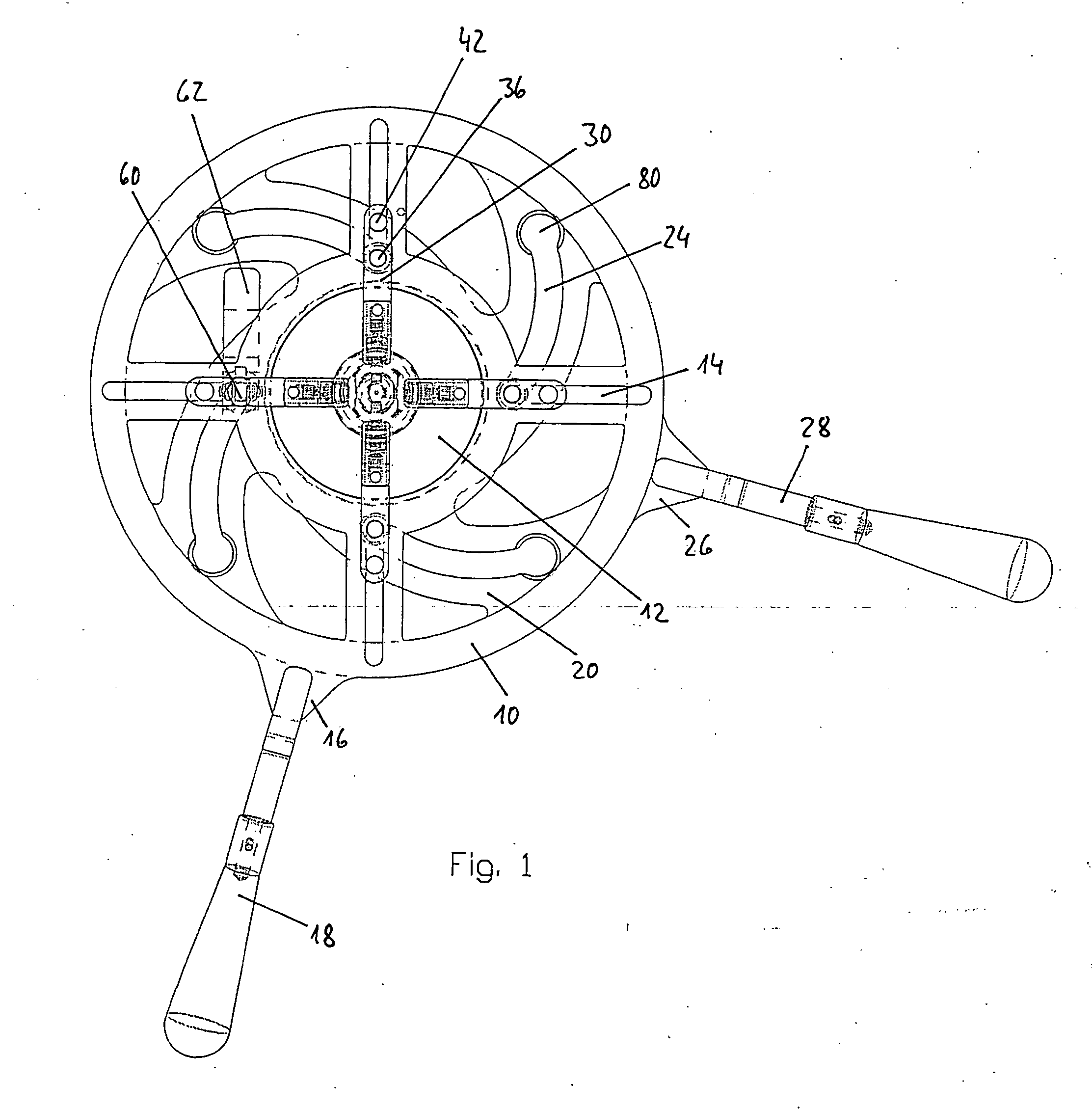
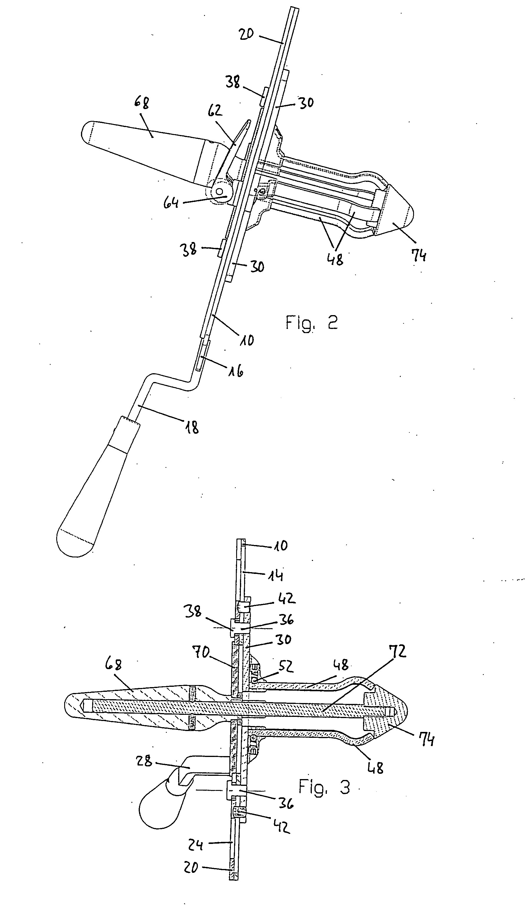
[0024] The anal retractor includes a base plate 10, which is shown in detail in FIG. 4. The base plate 10 has the shape of a circular disk with a central circular free opening 12. The opening 12 defines the cross-section of free access and exhibits a diameter of, for example, 60 mm. Radial guides run outside of the opening 12, in the form of guide slots 14 extending through the base plate 10. In the shown embodiment four guide slots 14 are provided, which are offset by 90° relative to each other with equal angular distribution. On it's circumference the base plate 10 exhibits a radially extending lobe 16, to which a radial projecting grip or handle lever 18 is secured, for example, by welding.

[0025] A rotor plate 20 lies against the proximal surface of the base plate 10, which is shown separately in detail in FIG. 5. The rotor plate 20 likewise has the shape of a circular disk, of which the outer diameter essentially corresponds with the outer diameter of the base plate 10. In the ...


PUM


Abstract

An anal retractor includes four retractor valves (48), which are offset 90° relative to each other and can be moved radially apart from each other. For this the four retractor valves (48) are guided by sleds (30) in radial guide slots (14) of a base plate (10). For movement of the sleds (30) guide bolts (36) extend through the radial guide slots (14) of the base plate (10) and spiral shaped actuating slots (24) of a rotor plate (20), which is rotatable relative to the base plate (10).

Description

BACKGROUND OF THE INVENTION [0001] 1. Field of the Invention [0002] The invention concerns an anal retractor according to the precharacterizing portion of claim 1. [0003] 2. Related Art of the Invention [0004] Anal retractors are used in order to dilate the anal canal for medical interventions and examinations. These anal retractors include retractor valves, which are introduced into the anal canal and then are moved apart for dilation of the anal canal. [0005] In one known embodiment two retractor valves are provided, which are spread apart using a scissors grip. Therewith only a comparatively small dilation of the anal canal is possible. Further, an anal retractor with two retractor valves is known, in which the one retractor valve is displaceable on a guide rail provided upon the other retractor valve. Therewith the retractor blades can, on the one hand, be spread further apart, the spreading of the anal canal occurs however only in diametrically opposed directions, so that the a...

Claims


Application Information

Patent Timeline
IPC IPC(8): A61B1/31A61B1/32
CPCA61B1/32A61B1/31
Inventor FEHLING, GUIDO
Owner AGILENT TECH INC
Why Eureka
Try Eureka