Circuit breaker

A circuit breaker and circuit technology, applied in the direction of circuits, electric switches, electrical components, etc., can solve problems such as wear and tear, and achieve the effect of improving contact ability

Active Publication Date: 2016-12-21
HITACHI ENERGY SWITZERLAND AG
View PDF5 Cites 0 Cited by
  • Summary
  • Abstract
  • Description
  • Claims
  • Application Information

AI Technical Summary

Problems solved by technology

Even though the fingers can still be used for subsequent operations, they wea

Method used


Image

  • Circuit breaker
  • Circuit breaker
  • Circuit breaker

Examples


Example Embodiment

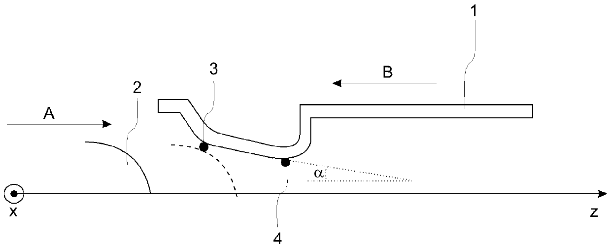
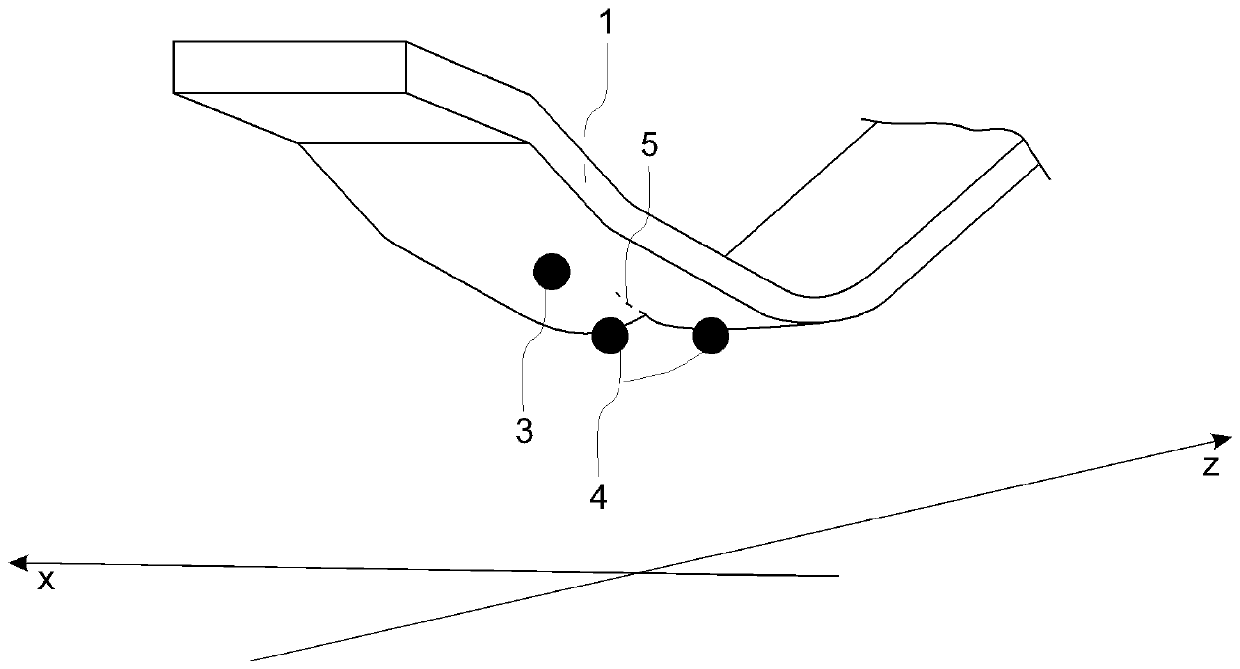
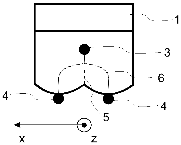
[0018] In the following, the same reference numerals denote structurally or functionally identical or similar elements of various embodiments of the present invention. Note that in the context of this document, contact "points" are not understood as points in a mathematical sense, but as small areas of mechanical contact. It is assumed that the coordinate system is a polar coordinate system with a longitudinal axis z and a radial axis x.

[0019] figure 1 Shows a simplified cross-sectional side view of the tube-type or rod-type contacts and mating contact fingers of the circuit breaker during the closing process, that is, during the closing operation, according to the present invention. The closing process is illustrated by arrows A and B. Arrows A and B show the contact finger 1 (which represents the first contact assembly 1, including the finger cage arranged around the longitudinal axis z) and the rod 2 (which represents the second The direction of movement of the contact ass...


PUM


Abstract

The invention relates to a circuit breaker comprising a first and a second contact assembly (1, 2), wherein one of the contact assemblies (1) comprises contact fingers arranged in a finger cage configuration and the other contact assembly (2) comprises a tube or rod contact. The contact fingers (1) comprise an impact point (3) where the tube or rod (2) impacts the contact fingers (1) for the first time during electrical connection establishment, and a contact zone which contacts the tube or rod (2) when the electrical connection is established. The contact zone comprises two contact points (4) separated from one another and arranged on a line which is perpendicular to the longitudinal axis (z).

Description

Technical field [0001] The invention is in the field of medium and high voltage switching technology and relates to a circuit breaker according to the independent claims. Background technique [0002] Circuit breakers are well known in the field of high voltage and medium voltage switchgear. They include nominal contacts and arc contacts, which are used to open and close electrical connections. During the opening and closing operations of the circuit breaker, the current commutates between the nominal and arc contacts and vice versa accordingly. For these operations, at least one nominal contact and one arc contact move relative to their corresponding mating contacts. It is also possible that both the nominal and arc contacts move towards each other. [0003] During the closing process, the arc contacts are connected first, and after that the nominal contacts are connected. The typical configuration of nominal contacts involves a tube or rod as the first nominal contact and con...

Claims


Application Information

Patent Timeline
IPC IPC(8): H01H1/38H01H1/44H01H1/50
CPCH01H1/385H01H1/44H01H1/50H01H33/02H01H1/06
Inventor F.皮苏F.伦德奎维斯特J.科贝J.科斯特森K.克鲁纳M.伦恩伯格S.科蒂赖恩
Owner HITACHI ENERGY SWITZERLAND AG
Why Eureka
Try Eureka