Automated inhalation toxicology exposure system and method

a toxicology and automatic inhalation technology, applied in the field of inhalant systems, can solve the problems of poor reproducibility of scientific experiments, poor control and/or monitoring of related-art inhalant systems, and poor control of inhalant delivery,

Inactive Publication Date: 2005-09-22
UNITED STATES OF AMERICA THE AS REPRESENTED BY THE SEC OF THE ARMY
View PDF60 Cites 7 Cited by
  • Summary
  • Abstract
  • Description
  • Claims
  • Application Information

AI Technical Summary

Problems solved by technology

The inventors have discovered that related-art inhalant systems tend to provide poor reproducibility of scientific experiments.
The inventors have noted that delivery of inhalants, environmental control, and monitoring in related-art inhalant systems is generally poorly controlled and / or monitored (e.g., by a human engaging in real-time manipulation of valves and motors and / or near real-time viewing and recordation of data presented on displays).
Accordingly, insofar as human actions tend to be notoriously difficult to reproduce, the inventors have concluded that related-art inhalant systems tend to provide poor reproducibility.
That is, precision and accuracy of inhalation experiments suffer because the users of related-art inhalant systems are neither able to exactly reproduce or actively record deviations of both intrinsic and extrinsic factors from experiment to experiment.
Unfortunately, related-art inhalant systems do not provide high reproducibility of scientific experiments.
Unfortunately, related-art inhalant systems are not, in general, capable of determining inhalant dosage via near real-time acquisition of respiration of a test animal.

Method used


Image

  • Automated inhalation toxicology exposure system and method
  • Automated inhalation toxicology exposure system and method
  • Automated inhalation toxicology exposure system and method

Examples


Embodiment Construction

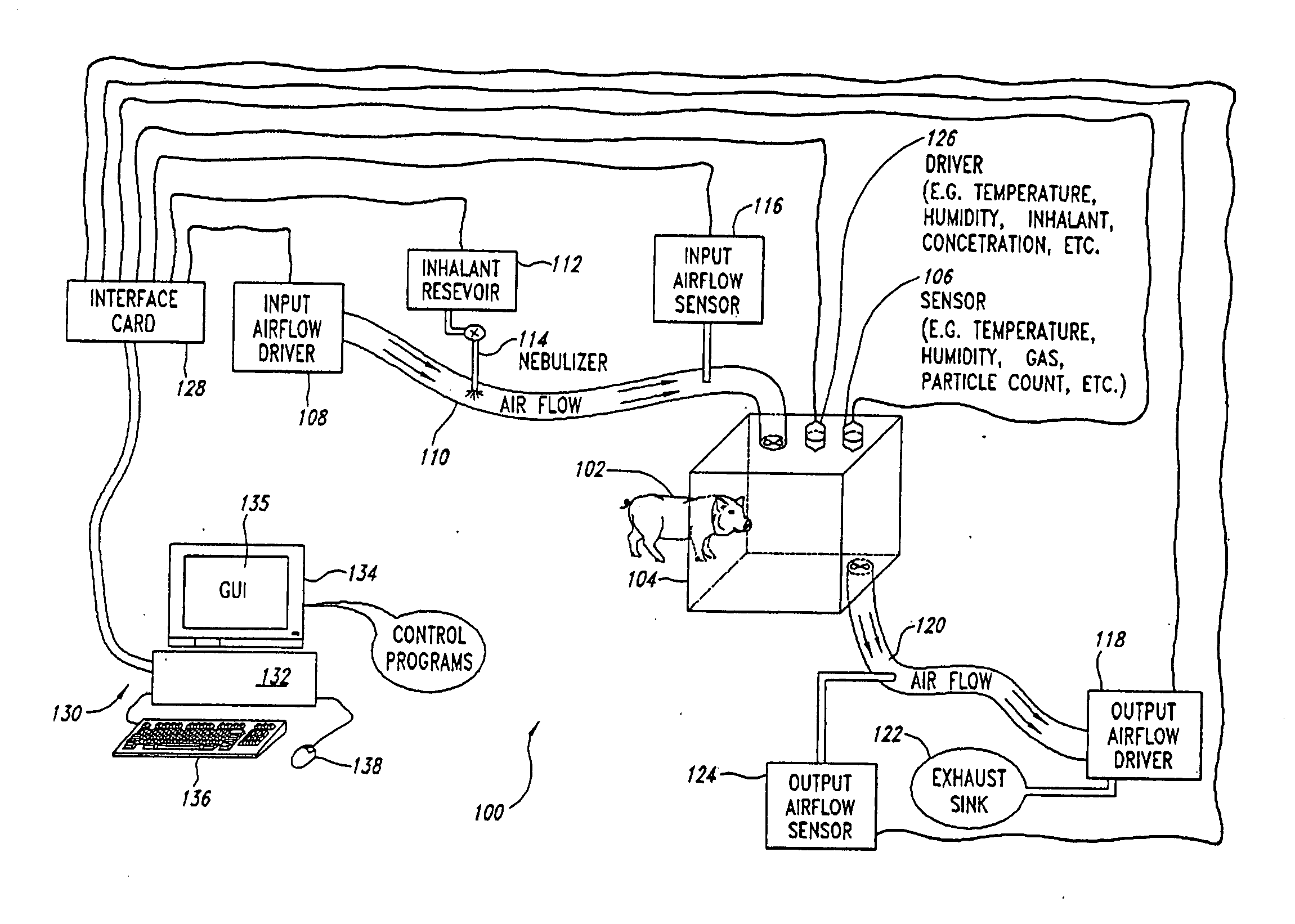
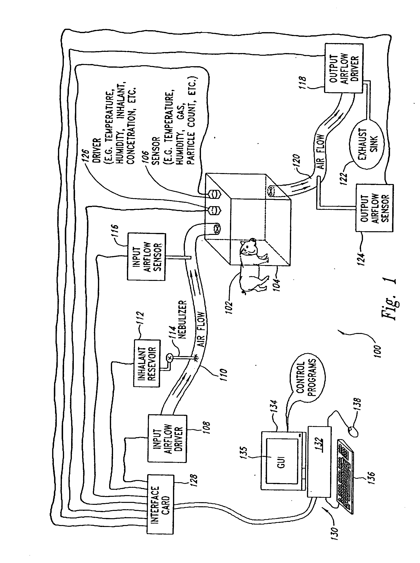
[0035] With reference now to FIG. 1, shown is a high level pictographic representation of inhalant exposure and monitoring system 100. Depicted is inhalant toxicology exposure system 100. Illustrated is animal 102 contained within inhalant chamber 104. Shown integral with inhalant chamber 104 is sensor 106, which is intended to be indicative of one or more types of sensors integral with various parts of inhalant toxicology exposure system 100. For example, sensor 106 is meant to be indicative of a variety of different types of sensors, such as temperature sensors, humidity sensors, particle count sensors, gas concentration sensors, etcetera, and even though sensor 106 is shown integral with inhalant chamber 104, sensor 106 is meant to be indicative of sensors positioned throughout various parts of inhalant toxicology exposure system 100.

[0036] Further with respect to FIG. 1, depicted is input airflow driver 108 (e.g., an air pump) connected to drive air through input air hose 110 a...


PUM


Abstract

In one embodiment, a method includes but is not limited to exposing an animal to an inhalant; acquiring near real time measurement of at least respiration during said exposing; and calculating a received dose of the inhalant in response to the near real time measurement of the at least respiration during said exposing. In one embodiment, a method includes but is not limited to automatically controlling an environment of an inhalant chamber; and automatically controlling a concentration of an inhalant in the inhalant chamber. In one embodiment, a method includes but is not limited to displaying near real time measurement data related to an animal in an inhalant chamber. In addition to the foregoing, other method embodiments are described in the claims, drawings, and text forming a part of the present application. In one or more various embodiments, related systems include but are not limited to circuitry and / or programming for effecting the foregoing-described method embodiments; the circuitry and / or programming can be virtually any combination of hardware, software, and / or firmware configured to effect the foregoing-described method embodiments depending upon the design choices of the system designer. In one embodiment, a system includes but is not limited to at least one inhalant chamber; and at least one animal respiration sensor integral with the at least one inhalant chamber.

Description

I. CROSS-REFERENCE(S) TO RELATED APPLICATION(S) [0001] This patent application is a continuation application of U.S. application Ser. No. 09 / 919,741, filed Jul. 31, 2001, which claims the benefit of U.S. Provisional Application No. 60 / 267,233, filed Jan. 31, 2001. These patent applications are hereby incorporated by reference.II. FIELD OF THE INVENTION [0002] The present application relates, in general, to inhalant systems. III. BACKGROUND OF THE INVENTION [0003] Inhalation exposure studies are generally performed using inhalant systems. In an inhalation exposure study, an animal is usually exposed to an organic or inorganic inhalant within the confined space of an inhalant chamber forming part of an inhalant system. [0004] In the related art, an inhalant system is typically one that provides mechanisms for exposing an animal to an inhalant. The inventors named herein (“inventors”) have noticed several deficiencies and / or unmet needs associated with related-art inhalant systems, a f...

Claims


Application Information

Patent Timeline
Patent Type & Authority Applications(United States)
IPC IPC(8): A01K1/03A61B5/08A61D7/04
CPCA01K1/031A61D7/04A61B5/0806
Inventor ROY, CHAD J.HARTINGS, JUSTIN M.
Owner UNITED STATES OF AMERICA THE AS REPRESENTED BY THE SEC OF THE ARMY
Why Eureka
Try Eureka