Image forming apparatus and process cartridge

a technology of image forming apparatus and process cartridge, which is applied in the direction of electrographic process apparatus, corona discharge, instruments, etc., can solve the problems affecting the effect of reducing the size of the developing device, and preventing the degradation of the photoreceptor surfa

Active Publication Date: 2005-11-03
RICOH KK
View PDF16 Cites 12 Cited by
  • Summary
  • Abstract
  • Description
  • Claims
  • Application Information

AI Technical Summary

Benefits of technology

[0012] An object of the present invention is to provide an image forming apparatus and a process cartridge in which a charging system that uses adjacent discharge is employed, wherein the image forming apparatus is n

Problems solved by technology

However, it has been learned that the photoreceptor surface is degraded due to the electrical discharge being concentrated in the vicinity of the photoreceptor surface in a charging system that uses adjacent discharge.
Although durability against mechanical abrasion is enhanced with this type of configuration, this type of configuration still cannot prevent chemical degradation of the photoreceptor surface by adjacent discharge.
However, when such a protective substance is applied to the photoreceptor surface, the toner and the photoreceptor surface come into contact with each other at the developing part, whereby the inside of the developing device can become contaminated with the protective

Method used


Image

  • Image forming apparatus and process cartridge
  • Image forming apparatus and process cartridge
  • Image forming apparatus and process cartridge

Examples


first embodiment

[0043] Following is a description of the present embodiment, which is obtained by applying the present invention to the image forming apparatus.

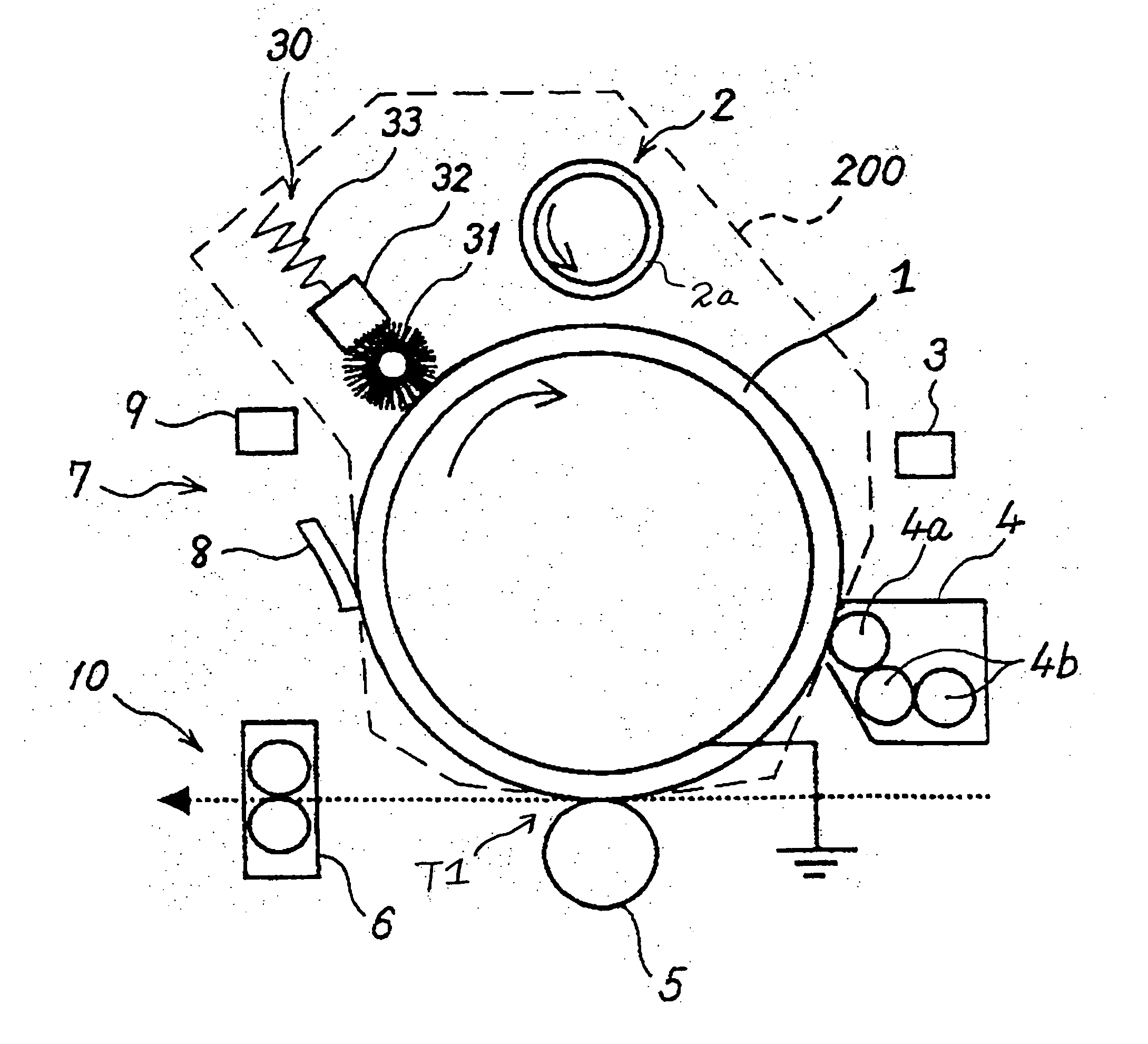
[0044] First, the basic structure of the image forming unit provided with the image forming apparatus will be described using FIG. 1. In FIG. 1, this image forming unit is made up of a drum-shaped photoreceptor 1 as an image carrier; a charging device 2; an exposing device 3 for inscribing an electrostatic latent image on the photoreceptor 1; a developing device 4; a cleaning device 7 for removing the image forming substance from the surface of the photoreceptor 1; and other components.

[0045] In the image forming apparatus thus configured, the photoreceptor 1 is rotatably driven by a driving device not shown in the drawing, and the surface thereof is charged in the prescribed polarity by the charging device 2. The exposing device 3 is then driven based on image information read from the outside, whereby an electrostatic latent image is for...

second embodiment

[0199] The present embodiment will be described in detail hereinafter with reference to the drawings.

[0200] Since FIGS. 1 through 6, 13, 14, and 16 referenced in the first embodiment above and most of the description relating thereto can also essentially be applied to the present embodiment, redundant description thereof is avoided to the extent possible, but some description will still be given that somewhat overlaps that of the first embodiment above.

[0201] First, the two-component developer according to the present embodiment composed of a toner and a carrier will be described.

[0202] A carrier in which a coating layer is formed as needed on a nucleus particle having magnetic properties is in common use.

[0203] A known magnetic particle has conventionally been used as the nucleus particle, and examples thereof may include iron, cobalt, nickel, and other ferromagnetic metals, as well as magnetite, hematite, ferrite, and other alloys or compounds.

[0204] Resins used in the coatin...


PUM


Abstract

In an image forming apparatus that employs a system of charging by adjacent discharge, not only can degradation of the photoreceptor surface caused by adjacent discharge be prevented, but also there is no side effect on the developer, and at the same time size reduction is achieved. The image forming apparatus comprises an object to be charged whose surface moves; a charging device for charging the object to be charged using an electrical discharge generated by applying a voltage comprising an alternating current component to a charging member provided in contact with or in proximity to the object to be charged; a latent image forming device for forming an electrostatic latent image on the surface of the object charged by the charging device; and a developing device for causing a two-component developer to come into contact with the image portion of the electrostatic latent image formed by the latent image forming device and affixing toner thereto. A protective substance is present on the surface of the object to be charged in the discharge region for charging the object to be charged, and the saturation magnetization of the carrier of the two-component developer with respect to an applied magnetic field of 1000 oersted is 40 to 80 emu/g.

Description

BACKGROUND OF THE INVENTION [0001] 1. Field of the Invention [0002] The present invention relates to a copy machine, laser printer, facsimile device, or other image forming apparatus, and to a process cartridge thereof. [0003] 2. Description of the Related Art [0004] The type of image forming apparatus that employs an electrophotographic process has conventionally had a charging device for charging the surface of a photoreceptor as an image carrier. A charging system that uses adjacent discharge is one example of a charging system used in the charging device. This is a system for charging the surface of a photoreceptor by adjacent discharge in which a charging member is brought into contact with, or brought near but not into contact with, the photoreceptor surface. Since increased resolution, miniaturization, and other features have been increasingly desired in recent years, increased resolution and small size have become objects in the charging device. A charging device with an adj...

Claims


Application Information

Patent Timeline
IPC IPC(8): G03G9/08G03G9/107G03G15/00G03G15/02
CPCG03G9/0821G03G9/0823G03G9/0827G03G2221/1609G03G15/02G03G2215/02G03G2215/0609G03G9/107
Inventor NAKAI, HIROSHISUZUKI, YASUOTAMOTO, NOZOMUTOKUMASU, TAKAHIKOWATANABE, KAZAHIKOOHSHIMA, KOHICHITSUKUDE, NOBORUMATSUURA, NEKKAIKUNO, HIROSHI
Owner RICOH KK
Why Eureka
Try Eureka