

Receiving processing method and apparatus
a processing method and receiving apparatus technology, applied in the field of receiving processing methods and receiving apparatuses, can solve the problems of increasing the delay wave amount, deteriorating reception characteristics, increasing the signal propagation distance, etc., and achieves the effect of suppressing the size of the apparatus, effective use of guard intervals, and efficient improvement of reception characteristics
- Summary
- Abstract
- Description
- Claims
- Application Information
AI Technical Summary
Benefits of technology
Problems solved by technology
Method used
Image

Examples
first embodiment
[1] First Embodiment
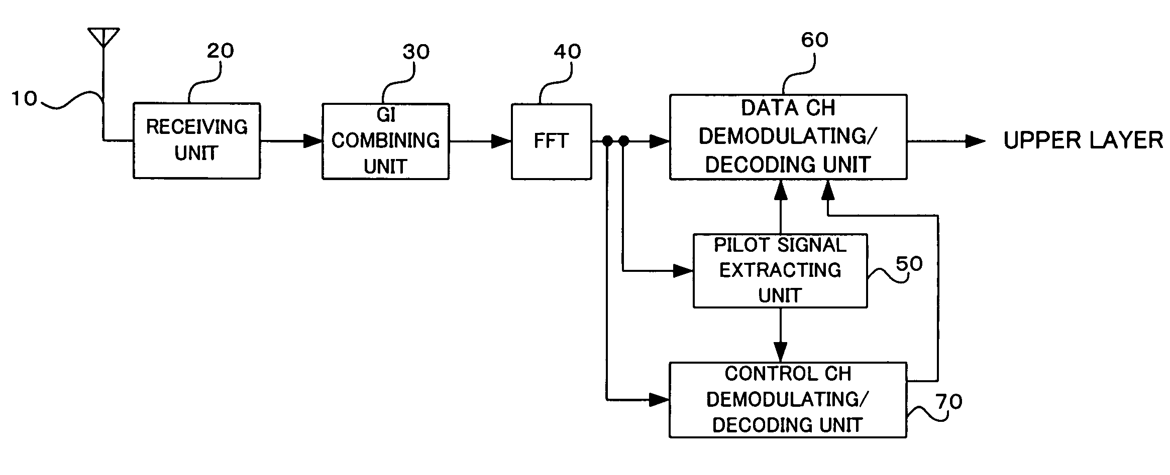
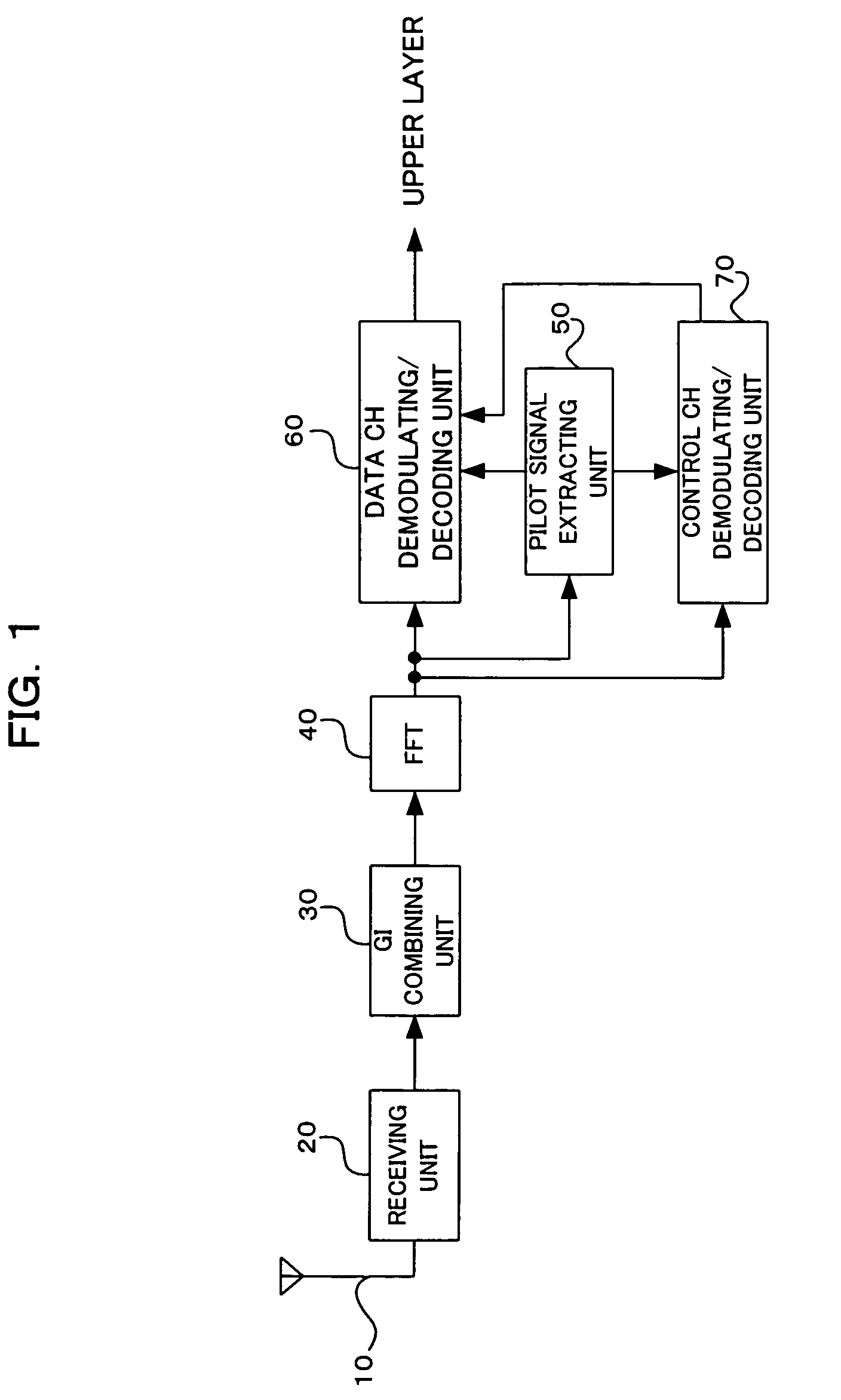
[0048]FIG. 1 is a block diagram showing an essential part of an OFDM receiving apparatus according to a first embodiment of the present invention. The OFDM receiving apparatus of the first embodiment of FIG. 1 includes e.g., a receiving antenna 10, a receiving unit 20, a guard interval (GI) combining unit 30, an FFT processing unit 40, a pilot signal extracting unit 50, a data channel (CH) demodulating / decoding unit 60, and a control channel demodulating / decoding unit 70.
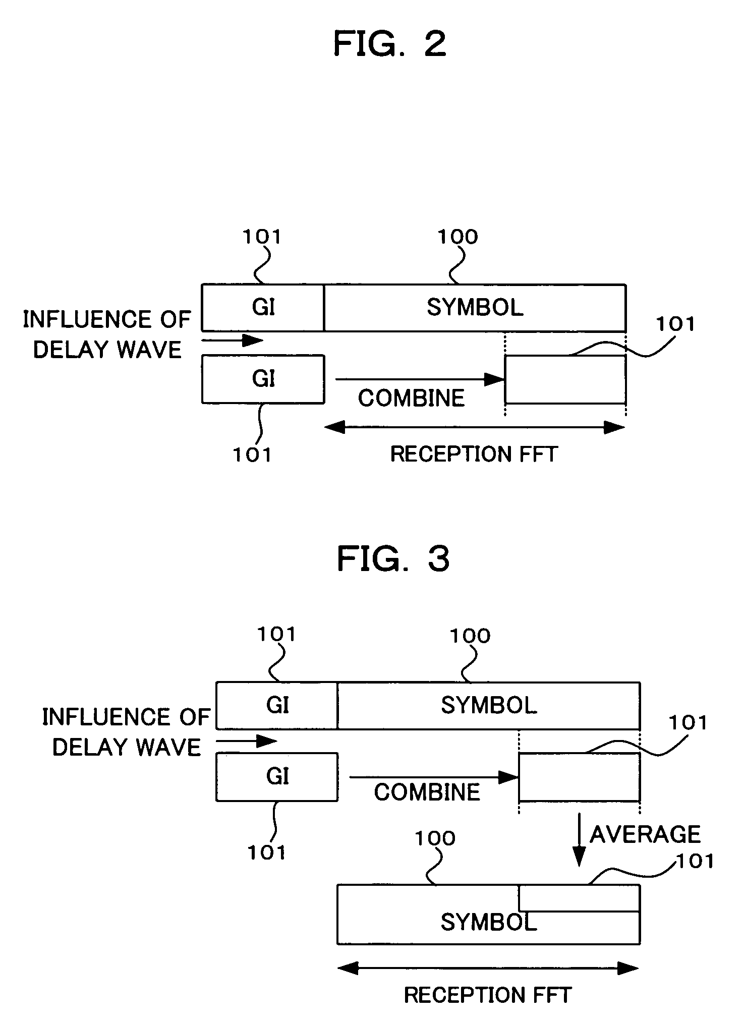
[0049] The receiving unit (receiver means) 20 receives a radio frequency (RF) signal (OFDM signal) through the receiving antenna 10 and performs necessary processing, such as downconversion to an intermediate frequency (IF) signal, A / D conversion, and orthogonal demodulation, on the received signal. The GI combining unit (guard interval combining means) 30, as shown in FIG. 2, simply combines the whole guard interval 101 of the received signal with a received symbol (valid symbol portion 100) wh...
second embodiment
[2] Second Embodiment
[0056]FIG. 4 is a block diagram showing an essential part of an OFDM receiving apparatus according to a second embodiment of the present invention. The OFDM receiving apparatus of FIG. 4 differs from the apparatus of FIG. 1 in that it has a GI processing unit 30′ in place of the GI combining unit 30, and in that it also has a combination evaluating unit 80A. Here, like reference numbers and characters designate similar parts or elements throughout several views of the present embodiment and the conventional art, so their detailed description is omitted here.
[0057] The GI processing unit 30′ selectively combines the whole guard interval 101 of the received signal with the valid symbol portion 100, depending on the evaluation result (an instruction of combination or removal) of the combination evaluating unit 80A. Upon receipt of an instruction to combine the guard interval 101, the GI processing unit 30′ combines the whole guard interval 101 with the valid symbo...
third embodiment
[3] Third Embodiment
[0067]FIG. 7 is a block diagram showing an essential part of an OFDM receiving apparatus according to a third embodiment of the present invention. The OFDM receiving apparatus of FIG. 7 differs from the apparatus of FIG. 4 in that it has a combination evaluating unit 80B in place of the combination evaluating unit 80A of FIG. 4.
[0068] The combination evaluating unit 80B receives information (coding rate information) relating to the coding rate (1 / 3, 1 / 2, 3 / 4, etc.) on the transmitter end which is included in the control channel modulated and decoded by the control channel demodulating / decoding unit 70, and evaluates whether or not the whole guard interval is to be combined (by simple addition or averaging) with the valid symbol portion 100 based on the coding rate information, and notifies the GI processing unit 30′ of the evaluation result (combination or removal). For example, when the coding rate=1 / 3 or =1 / 2, a combination instruction is notified to the GI pr...
PUM
 Abstract
Description
Claims
Application Information