Optical apparatus

a technology of optical devices and optical transmission lines, applied in the field of optical devices, can solve the problems of difficult to reduce the size of the device, increase in the cost of the optical isolator, and increase in the cost of the optical passive device, so as to reduce the number of optical devices, reduce the size and cost of the device, and improve the quality of the optical transmission.

Inactive Publication Date: 2005-12-08
FUJITSU LTD
View PDF11 Cites 17 Cited by
  • Summary
  • Abstract
  • Description
  • Claims
  • Application Information

AI Technical Summary

Benefits of technology

[0016] The present invention was created in view of the above circumstances, and an object thereof is to provide an optical apparatus which is reduced in the number of op

Problems solved by technology

However, an optical isolator is one of the most expensive optical passive devices and entails an increase in cost (in the optical amplifier 100, an expensive

Method used


Image

  • Optical apparatus
  • Optical apparatus
  • Optical apparatus

Examples


Embodiment Construction

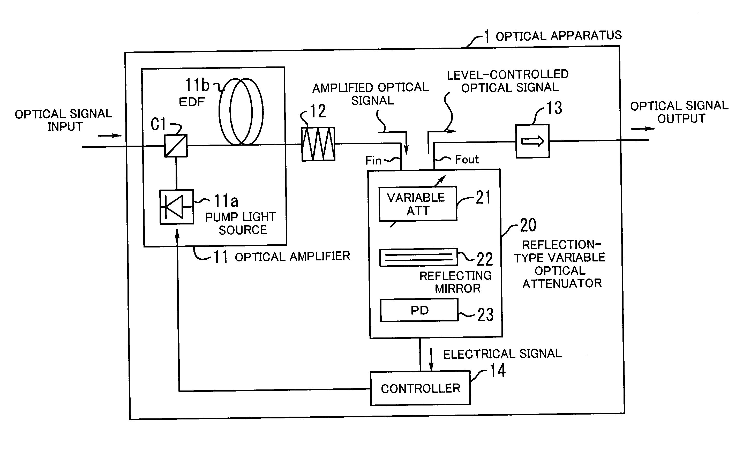
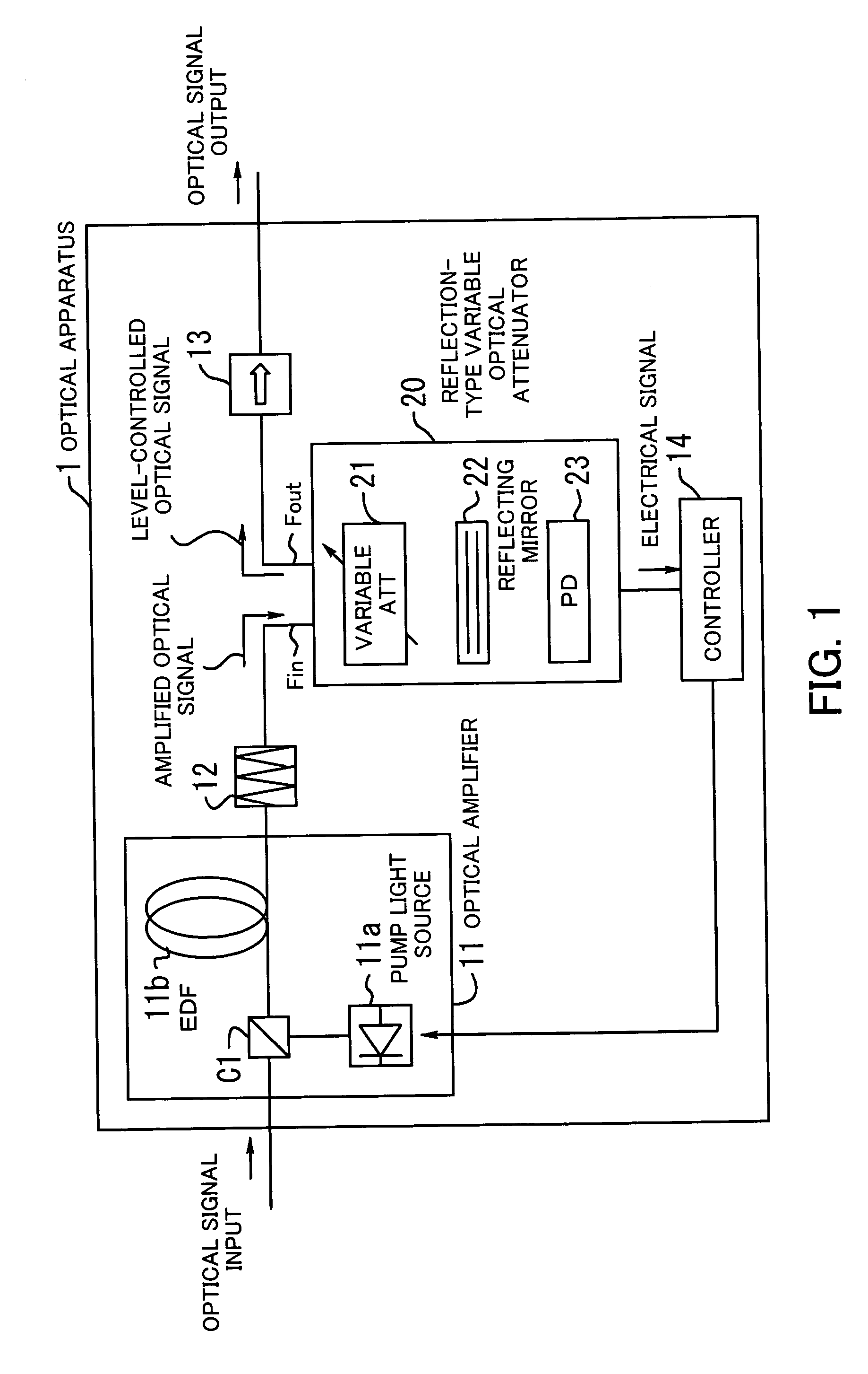
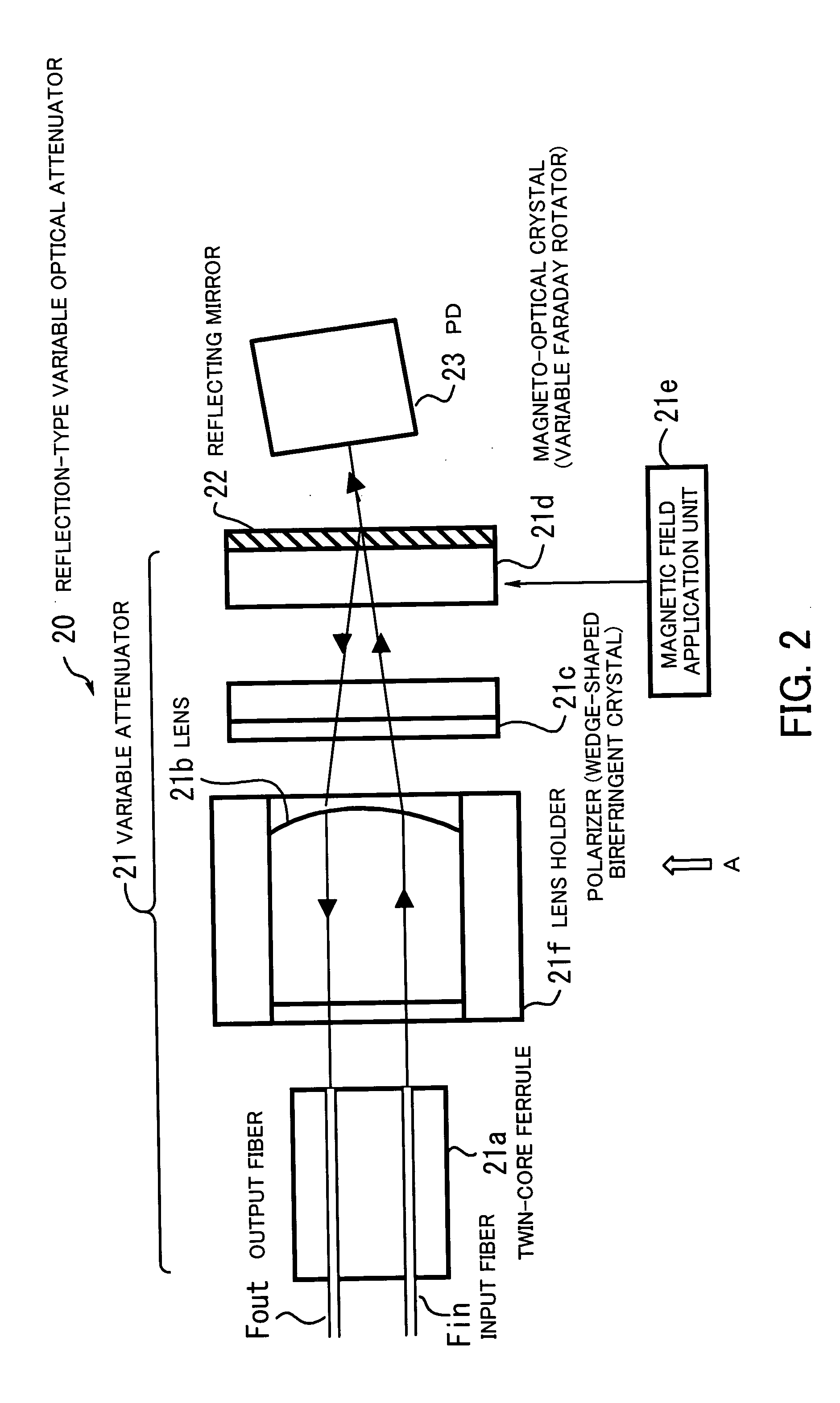
[0031] Preferred embodiments of the present invention will be described below with reference to the accompanying drawings, wherein like reference numerals refer to like elements throughout. FIG. 1 illustrates the principle of an optical apparatus according to the present invention. The optical apparatus 1 comprises an optical amplifier 11, a gain equalizer 12, an optical isolator 13, a controller 14, and a reflection-type variable optical attenuator 20. The optical amplifier 11 includes a pump light source 11a, an EDF 11b, and a coupler C1. The reflection-type variable optical attenuator 20 includes a variable attenuator 21, a reflecting mirror 22, and a light-receiving element (PD) 23.

[0032] In the optical amplifier 11, pump light from the pump light source 11a is introduced, via the coupler C1, into an amplification medium (hereinafter EDF) doped with an active material for optical amplification (the pump light has a wavelength band of 1 micron or less, e.g., 0.98 microns). Conse...


PUM


Abstract

An optical apparatus which is reduced in the number of optical devices arranged on a main optical signal transmission path, thereby reducing the size and cost of the device, and which is improved in optical transmission quality. An optical amplifier includes an amplification medium, which is doped with an active material for optical amplification and to which pump light is introduced, for amplifying an optical signal to be output. A reflection-type variable optical attenuator includes a reflecting mirror for reflecting an input light to generate a reflected light, and a magneto-optical crystal arranged in a position where the input and reflected lights pass. The magneto-optical crystal is applied with a magnetic field to induce a Faraday rotation angle therein and thereby vary an attenuation amount of the amplified optical signal, and part of light transmitted through the reflecting mirror is converted, as input monitor light, into an electrical signal.

Description

[0001] This application is a continuing application, filed under 35 U.S.C. § 111(a), of International Application PCT / JP2003 / 008063, filed Jun. 25, 2003.BACKGROUND OF THE INVENTION [0002] 1. Field of the Invention [0003] The present invention relates to optical apparatus, and more particularly, to an optical apparatus for amplifying an optical signal. [0004] 2. Description of the Related Art [0005] In recent years, much attention and development are directed to DWDM (Dense Wavelength Division Multiplexing) which permits a single optical fiber to accommodate several tens to several hundreds of wavelength channels each capable of transmitting data at high rates of 600 Mbps to 10 Gbps, thereby enabling data transmission of an extremely large total capacity of the order of Tbps. [0006] In optical amplification techniques for WDM systems including DWDM, EDFA (Erbium-Doped Fiber Amplifier) is widely used. EDFA is an optical amplifier using an EDF (Erbium (Er3+)-Doped Fiber) as an amplific...

Claims


Application Information

Patent Timeline
IPC IPC(8): G02F1/01G02F1/09H01S3/00H01S3/067H01S3/094H01S3/0941H01S3/10H01S3/13H01S3/16
CPCG02F1/0123G02F1/093H01S3/005H01S3/0064H01S3/06754H01S3/06758H01S3/094015H01S3/10015H01S3/10023H01S3/1305H01S3/1608H04B10/2931H04B10/2941
Inventor SHUKUNAMI, NORIFUMINAGANUMA, NORIHISASUZUKI, YUICHIISHIWADA, TAKASHI
Owner FUJITSU LTD
Why Eureka
Try Eureka