Non-slip shoulder pad and strap

a strap and shoulder technology, applied in the field of shoulder straps, can solve the problems of strap pad slipping off the shoulder, into the shoulder, and the user's carrying heavy bags has always been wearisome, and achieve the effects of minimizing slippage, easy removal or attachment, and maximum comfor

a strap and shoulder technology, applied in the field of shoulder straps, can solve the problems of strap pad slipping off the shoulder, into the shoulder, and the user's carrying heavy bags has always been wearisome, and achieve the effects of minimizing slippage, easy removal or attachment, and maximum comfor

US20060000858A1Inactive Publication Date: 2006-01-05JUNG MAN YOUNG

Image

  • Non-slip shoulder pad and strap
  • Non-slip shoulder pad and strap
  • Non-slip shoulder pad and strap

Examples


Embodiment Construction

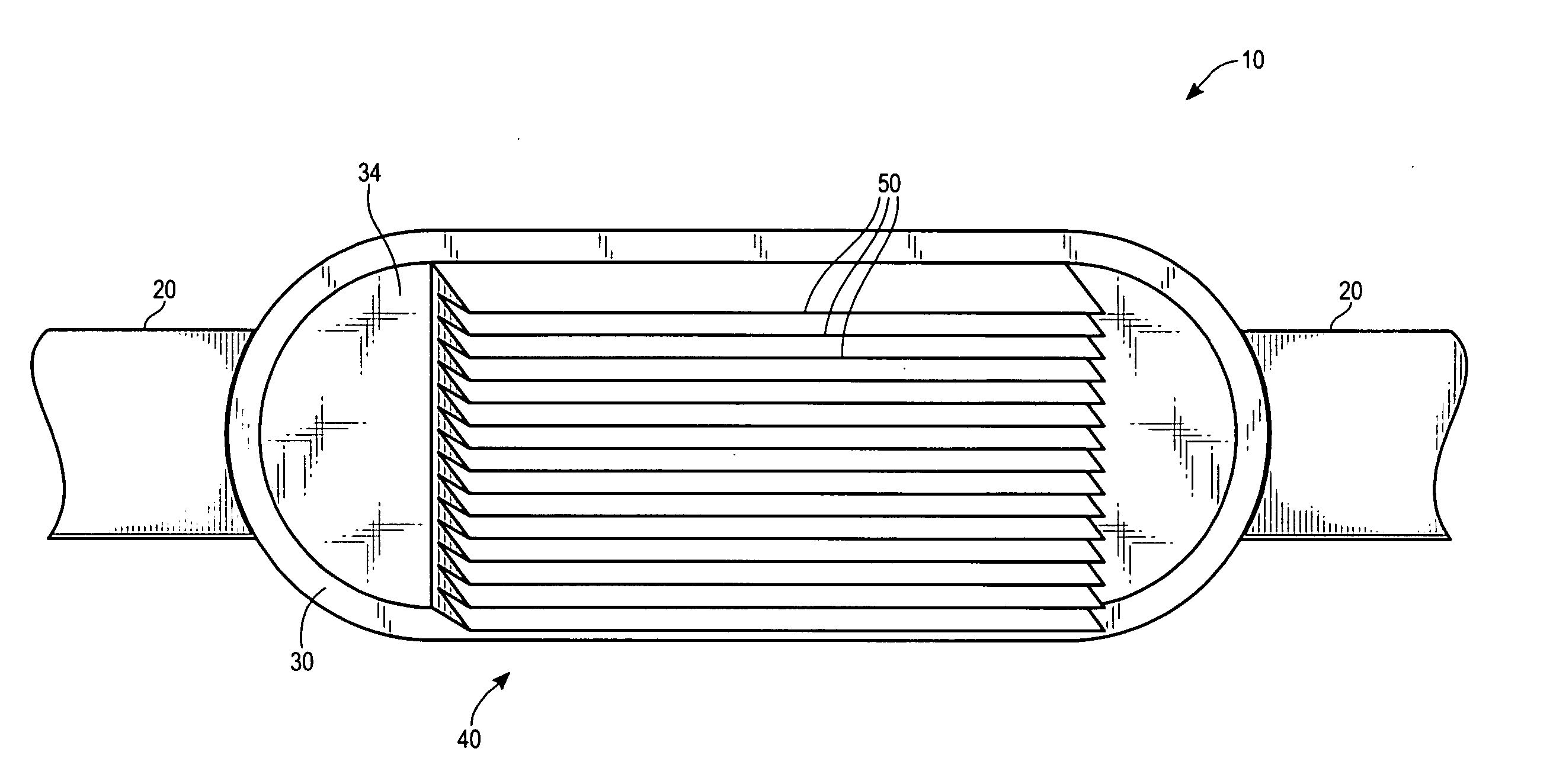
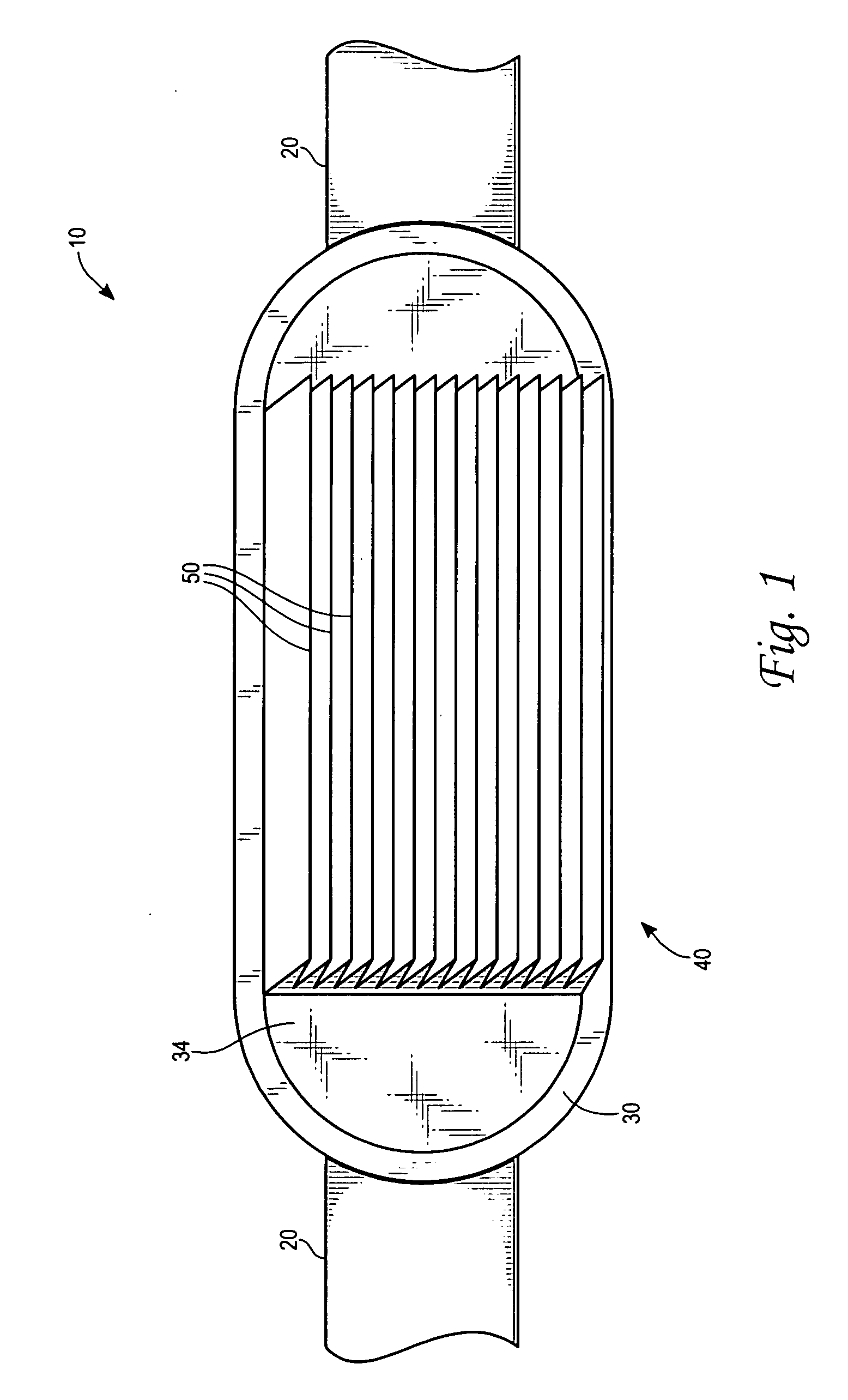
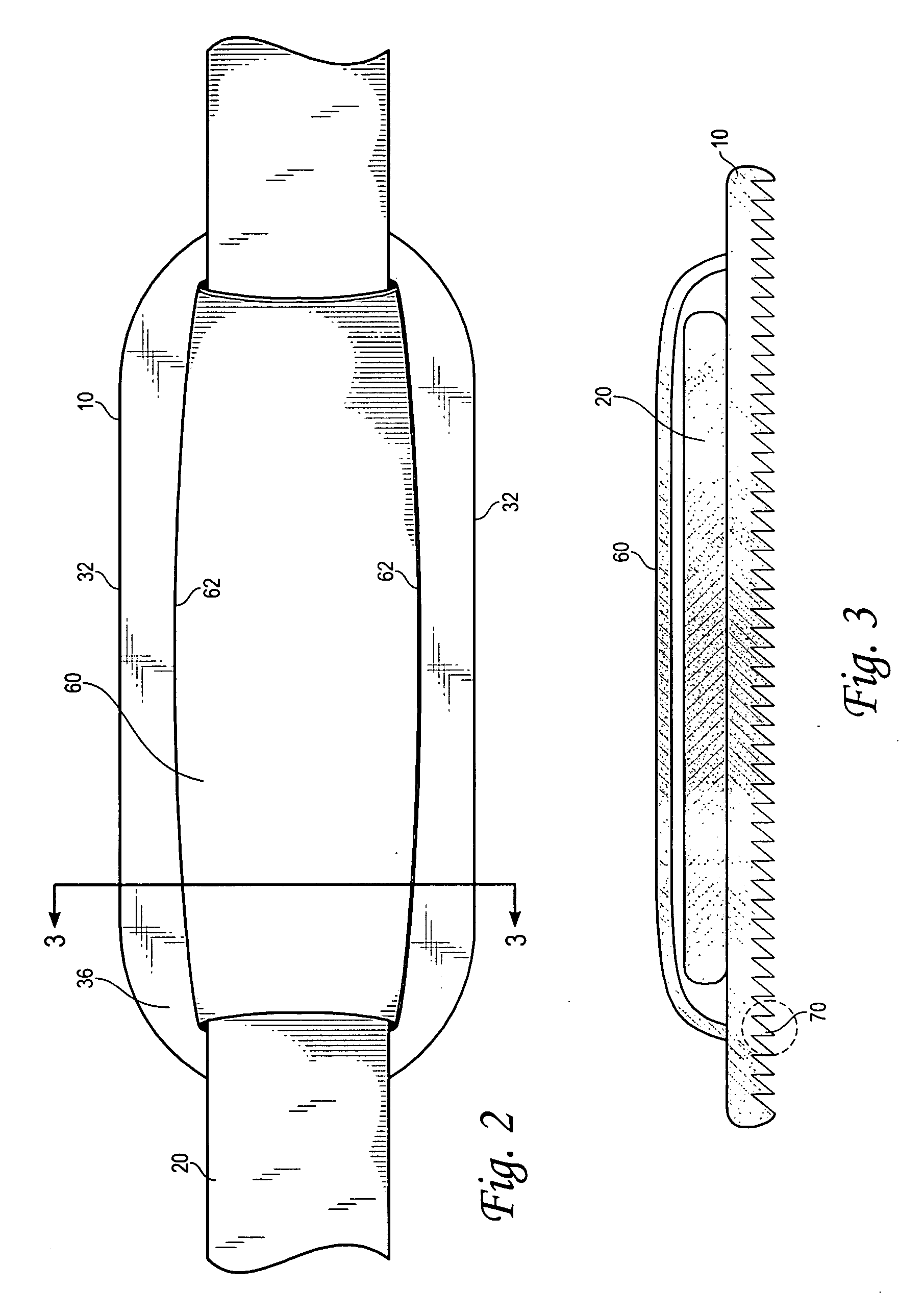
[0020] The present invention is a non-slip pad 10 for attaching to a shoulder strap 20 (FIG. 1), such as those formed from a generally flat nylon material. The pad 10 comprises an elongated generally flat base 30 having a non-slip pattern 40 formed into a front side 34 thereof. The non-slip pattern 40 comprises a plurality of ridges 50 each having either a triangular cross-section 70 or a trapezoidal cross-section 80 (FIGS. 4A-D). The non-slip pad 10 is generally rectangular in shape, but may preferably have rounded corners (FIGS. 1 and 2).

[0021] An elongated generally flat rectangular strap holder 60 is attached at each of a longer side 62 thereof proximate to a longer side 32 of a back side 36 of the base 30 (FIG. 2). The strap holder 60 slidably holds the shoulder strap 20 between the strap holder 60 and the base 30. As such, the non-slip pad 10 may be slidably adjusted with respect to the shoulder strap 20 for optimal comfort and carrying ease of the user. The strap holder 60 m...


PUM


Abstract

A non-slip pad for attaching to a shoulder strap of a bag, such as a golf bag, is disclosed. The pad comprises an elongated generally flat base having a non-slip pattern formed into a front side thereof. The non-slip pattern comprises a plurality of ridges each having either a triangular cross-section or a trapezoidal cross-section. The non-slip pad is generally rectangular in shape. An elongated generally flat rectangular elastic strap holder is attached to the backside of the base and slidably holds the shoulder strap between the strap holder and the base. As such, the non-slip pad may be slidably adjusted with respect to the shoulder strap for optimal comfort and carrying ease of the user. A non-slip strap comprising a strap and a non-slip pad are also disclosed.

Description

FIELD OF THE INVENTION [0001] The present invention relates to shoulder straps for carrying items such as bags, and more particularly to a non-slip shoulder pad incorporated into a carrying strap utilized on bags. DISCUSSION OF RELATED ART [0002] Carrying heavy bags has always been wearisome to the user. When a user has to carry such a bag and walk for some distance, such as when carrying a golf bag while walking a golf course, having a gripping handle or shoulder strap facilitates carrying. Although golf bags are typically provided with carrying handles for use over short distances, a shoulder strap provides more convenience and comfort for carrying such bags over longer distances. [0003] However, when the bags are relatively heavy, one of the problems encountered is the strap pad tends to slip off the shoulder as the user walks or otherwise moves. Further, such straps can dig into the shoulder and cause discomfort. [0004] Various attempts have been made in the prior art to provide...

Claims


Application Information

Patent Timeline
05 Jan 2006
Publication
US20060000858A1
IPC
A41F15/02; A45F3/12
CPC
A45F3/12
Inventors
JUNG, MAN-YOUNG