Combined wall treatment and bed

Inactive Publication Date: 2008-03-06
STOLTZFUS NATHAN LEE
View PDF26 Cites 19 Cited by
  • Summary
  • Abstract
  • Description
  • Claims
  • Application Information

AI Technical Summary

Benefits of technology

[0032] Existing wall beds typically use a common rigid surface to support the mattress, or, if they do incorporate a flexible mattress support, a saggy and uncomfortable wire and spring support is usually provided. In contrast, the combined wall treatment and bed of the invention uses state of the art thin flexible cambered slat technology, as used in most modern European sleep systems. The slats flex to follow movement and the pressure contours of one's body. A combined hybrid inflatable air mattress, preferably including foam in the air bladder with an additional foam topper, provides comfort while being light weight and compactly stored.
[0033] Existing Murphy beds do not have a mechanism to slow the rise of the bed as it reaches the vertical stored position, thus creating a situation

Problems solved by technology

When the unit is in the upright and stowed position its appearance is that of a thin (typically 4½″) wall treatment, the thickness of a large painting, and thus consumes practically no living space.
As noted above, while existing wall beds save a considerable amount of space as compared to the standard b

Method used


Image

  • Combined wall treatment and bed
  • Combined wall treatment and bed
  • Combined wall treatment and bed

Examples


Example

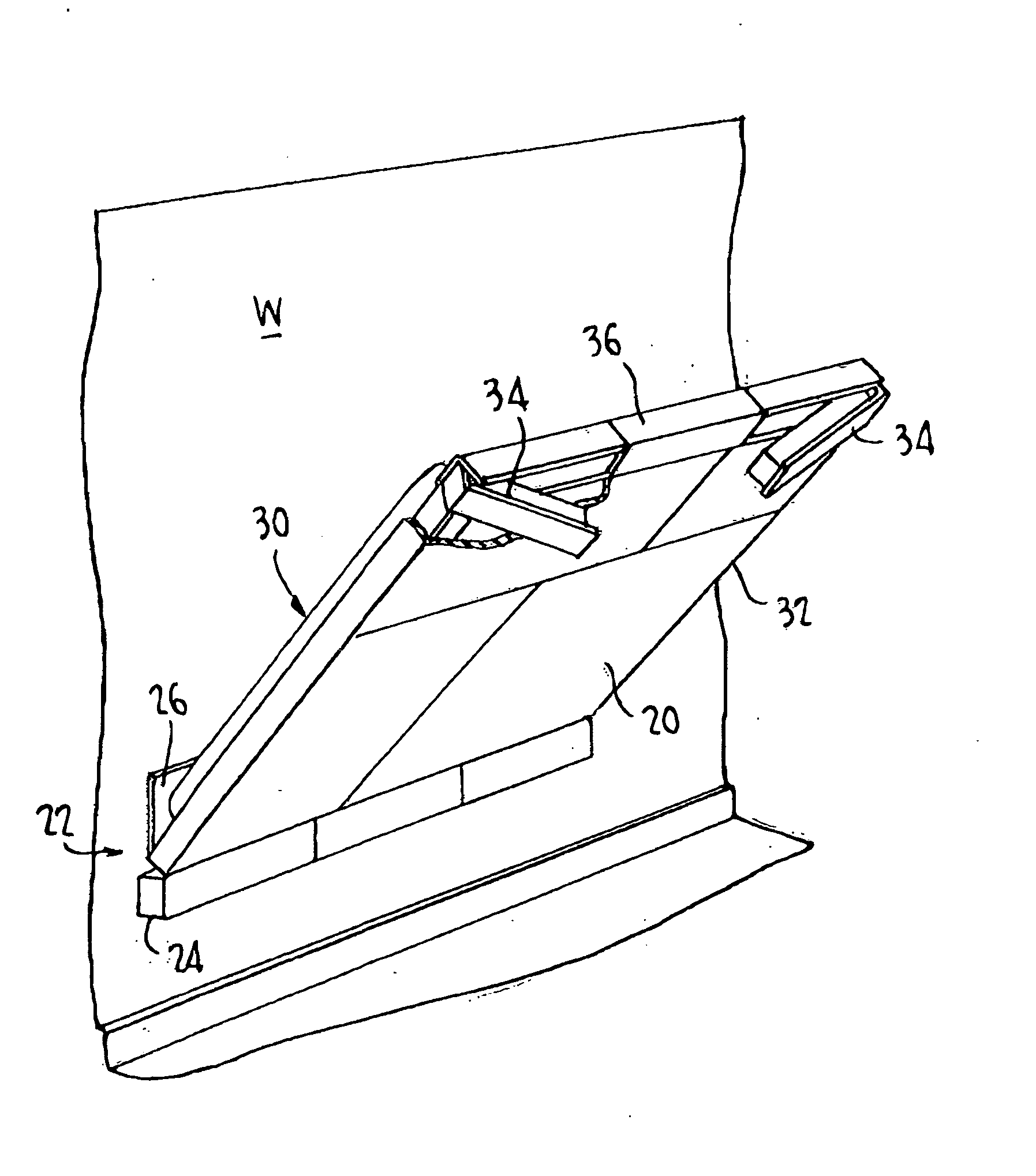
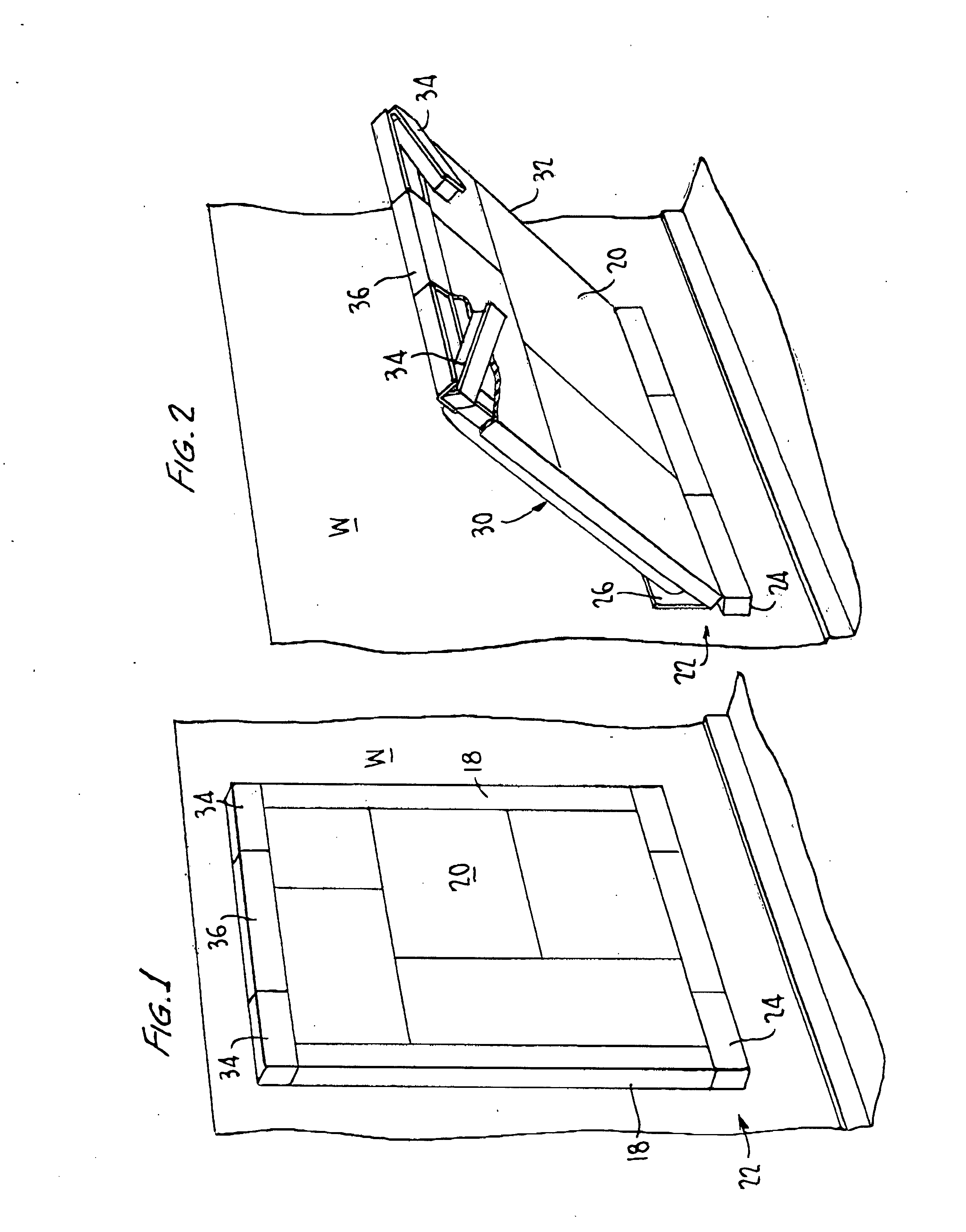
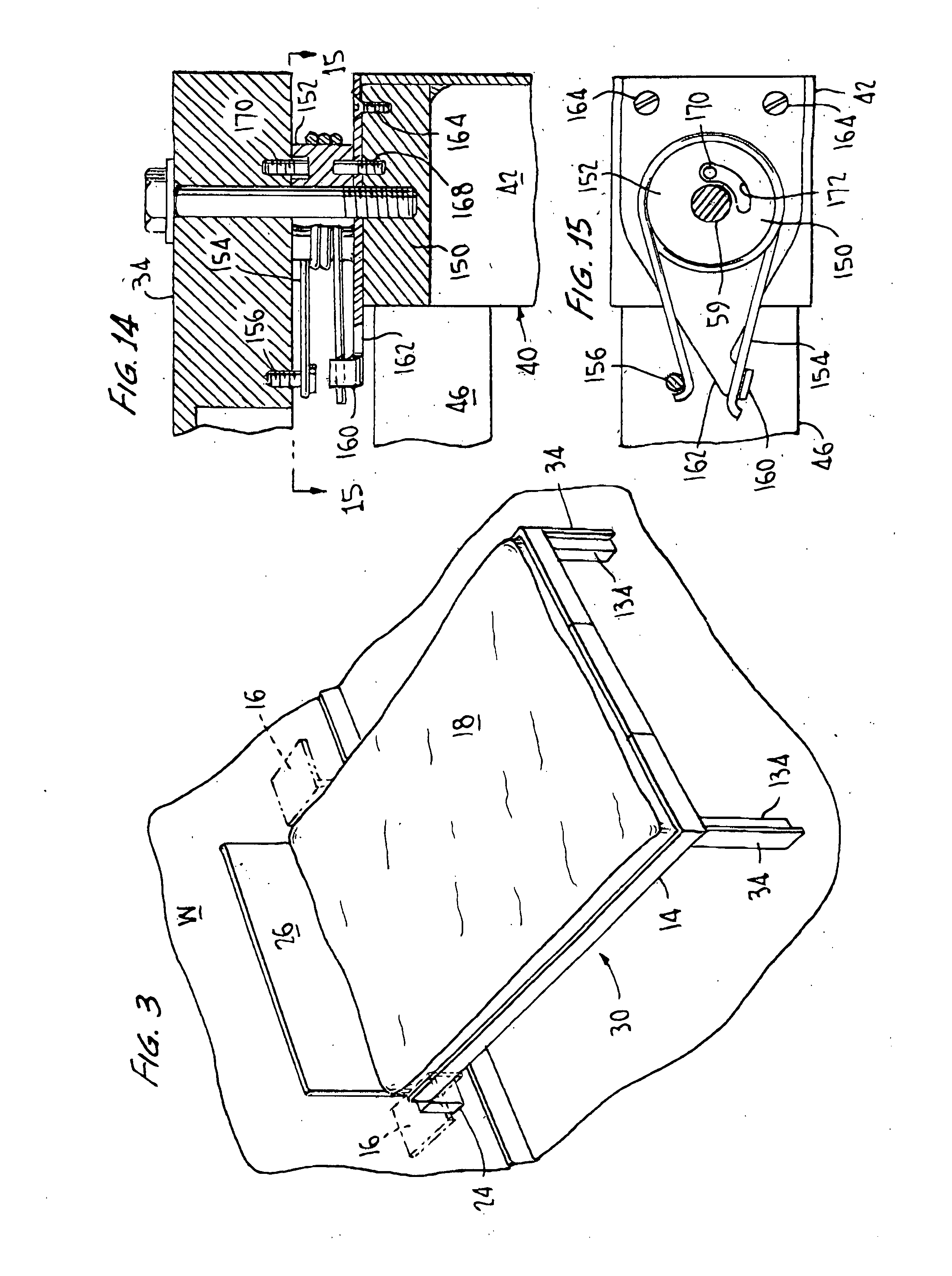
[0056] Referring now to the drawings and in particular to FIGS. 1, 2, and 3, these show overall views of the combined wall treatment and bed of the invention (sometimes “the unit” hereafter) in several positions. Specifically, FIG. 1 shows the unit in its raised and stowed position, in which it appears as a wall treatment. In this embodiment, the outer face or façade 20 of the unit, which forms the underside of the unit when lowered for sleeping, is shown as a paneled face. All manner of flat surface treatments may be applied to façade 20, including, without limitation, wood paneling, artwork, fabrics, bulletin boards, black- or white-boards, and the like. It is also within the invention to provide means for readily replacing one form of surface treatment with another, to enable easy redecoration. FIG. 2 shows the combined wall treatment and bed of the present invention in an intermediate position, as it is being lowered to the sleep position or raised to the stowed position. FIG. 3...


PUM


Abstract

A combined wall treatment and bed, that is, a unit which resembles a decorative wall treatment, such as a painting, when in the upright and stowed position, but which can be lowered to provide a comfortable bed. When the unit is in the upright and stowed position its appearance is that of a thin (4½″) wall treatment, the thickness of a large painting, and thus consumes practically no living space. A fixed component can be attached to any standard wall construction without modification; it supports the lower edge of a movable portion and defines an axis about which the movable portion pivots to provide a functional and comfortable bed. The fixed component of the unit comprises a lower horizontal element to conceal the support and pivot mechanism, and forms the lower component of a frame visually surrounding the center of the wall treatment; the corresponding upper element conceals a set of legs supporting the upper edge of the movable portion of the unit when in the lowered position. A planar center member between the upper and lower frame elements supports and conceals the sleep system, and can be decorated with a façade of wood, cloth, or painted treatments to taste. The legs, which are concealed in the upper frame element, automatically articulate out to support the foot of the bed as it reaches the horizontal position. A thin yet very comfortable bed is provided by a sleep system that utilizes a comfortable hybrid air and foam mattress. An electric air handling system automatically inflates the hybrid air and foam mattress as the bed begins its descent and deflates the mattress as the bed is pivoted to the vertical position, and preferably allows for pressure adjustment after the bed is down. The sleep system also uses thin flexible cambered slats, which both take up very little space and provide maximum comfort.

Description

CROSS-REFERENCE TO RELATED APPLICATION [0001] This application claims priority from provisional application Ser. No. 60 / 840,707, filed Aug. 29, 2006.FIELD OF THE INVENTION [0002] This present invention relates generally to a combined wall treatment and bed, that is, to a piece of furniture which can be readily converted from a thin, attractive wall treatment to a comfortable bed. BACKGROUND OF THE INVENTION [0003] Convertible furniture has long been known as a way to conserve floor and living space while providing temporary sleeping accomodations. It appears that William L. Murphy invented what is commonly known as the “Murphy bed” or the “wall bed” (these terms being used interchangeably herein) in the early 1900's, and versions of his design are still used today. The basic Murphy bed consists of a bed frame with a standard mattress. The bed frame pivots about an axis at or near the head of the bed from a stowed position in which the frame and mattress are juxtaposed to the wall to...

Claims


Application Information

Patent Timeline
IPC IPC(8): A47C17/38
CPCA47C17/40
Inventor STOLTZFUS, NATHAN
Owner STOLTZFUS NATHAN LEE
Why Eureka
Try Eureka