Rearview mirror assembly incorporating accessories

a rearview mirror and accessories technology, applied in the field of rearview mirror assemblies, can solve the problems of accidents or injuries, driver may not notice, and the display in the headliner mounted console is even more difficult to view, and achieves the effects of easy adaptability for attachment, easy readable, and light weigh

Inactive Publication Date: 2006-03-14
DONNELLY CORP
View PDF100 Cites 175 Cited by
  • Summary
  • Abstract
  • Description
  • Claims
  • Application Information

AI Technical Summary

Benefits of technology

[0019]In other aspects of the invention, an rearview mirror assembly is provided which is useful either with the above-mentioned support assembly of the present invention as well as with other interior rearview mirror supports. The rearview mirror assembly has a rearview mirror and a support for mounting the assembly on a vehicle. The rearview mirror has a driver side end and a passenger side end. The driver side end is adapted to be closer to the position of the vehicle driver when the assembly is mounted in a vehicle on the support. The passenger side end is adapted to be closer to the position of a front seat passenger in the vehicle when the assembly is mounted in the vehicle on the support. The rearview mirror also includes a reflective mirror element which has a front surface lying in a mirror plane and faces the interior of the vehicle, and a housing for the mirror element, the housing being adjustably mounted to the support and including a back portion facing away from the vehicle interior, end portions, and a front portion facing the vehicle interior. The assembly also includes an information display which provides information to an occupant of the vehicle. The display has a display plane which is at an angle to the mirror plane to provide improved visibility of the display by a front seat passenger in the vehicle when the assembly is mounted on the vehicle.
[0021]Advantages provided by this invention include adjustable support of a rearview mirror while providing information adjacent to the rearview mirror within the vehicle and visible by the vehicle operator and other vehicle occupants without obstructing the vehicle operator's normal field of view and without requiring major shift in the vehicle operator's line of sight to maintain adequate safety, the display preferably remaining fixed while the rearview mirror is adjusted about its pivot attachment to the support so that the driver can select the field of view for the reflective element housed within the rearview mirror independent of the viewing angle of the display attached to the mirror support and information support assembly. The combined mirror stay, support and information display is compact, light in weight and easily adaptable for attachment to the vehicle within the vehicle driver's line of sight, either by a windshield mounted button or a header mounted base. The information display is provided in an unobtrusive but easily readable format immediately adjacent the rearview mirror and can be provided with various types of emitting displays, audible signals or the like or passive displays. The electrical circuitry for the display is, preferably, substantially concealed as is the electrical wiring for connection of the assembly to the vehicle electrical system while also optionally providing concealed wiring for operation of electrically operated rearview mirrors including electro-optic mirrors, lighted mirrors and the like. In addition, the present information display can be coordinated easily with the remaining instruments and displays within the vehicle for automatic or manual operation or with intensity coordinated to the ambient lighting around the display and rearview mirror or in relation to the lighting on the instrument panel. In addition, inclusion of the electronics within the housing attached to the mirror stay allows for easy removal for servicing and positions the weight of the circuitry separately from the rearview mirror, thereby reducing vibration and oscillation and increasing visual clarity of the images in the mirror.
[0022]Additional advantages include the provision of an information display on the rearview mirror assembly adapted for ease of viewing and reading by a front seat passenger. Alternately, information displays can be included in the field of the reflective mirror element or on the peripheral edge of the mirror housing for the rearview mirror assembly, either separately from or in conjunction with the information display provided on the mirror support of the present invention.

Problems solved by technology

Such distraction can result in accident or injury, especially if the vehicle operator is presented with an emergency situation during such viewing.
Also, a driver may not notice illumination of a critical warning display relating to occupant safety or vehicle operation (such as of disablement of a passenger air bag) when the display is located in the instrument panel due to the information clutter caused by the great number of other displays commonly found in the instrument panel.
However, reference to the information in such consoles also requires a redirection of the viewer's line of sight from the road toward the vehicle roof.
Such redirection is even more pronounced in cab-forward automobile designs in which the head position of the vehicle operator is moved forward with respect to the windshield / headliner boundary such that the displays in the headliner mounted consoles are even more difficult to view.
The combined mirror and display in such constructions is also heavier than conventional mirrors resulting in increased vibration or oscillation and reduced quality images in the mirror surface.
However, depending on the size of the passenger, and the seat position with respect to the position of the interior rearview mirror assembly, information displays primarily intended for reading by the vehicle driver may be difficult to see or read by smaller size passengers with the seat moved to its far forward position.

Method used


Image

  • Rearview mirror assembly incorporating accessories
  • Rearview mirror assembly incorporating accessories
  • Rearview mirror assembly incorporating accessories

Examples


Embodiment Construction

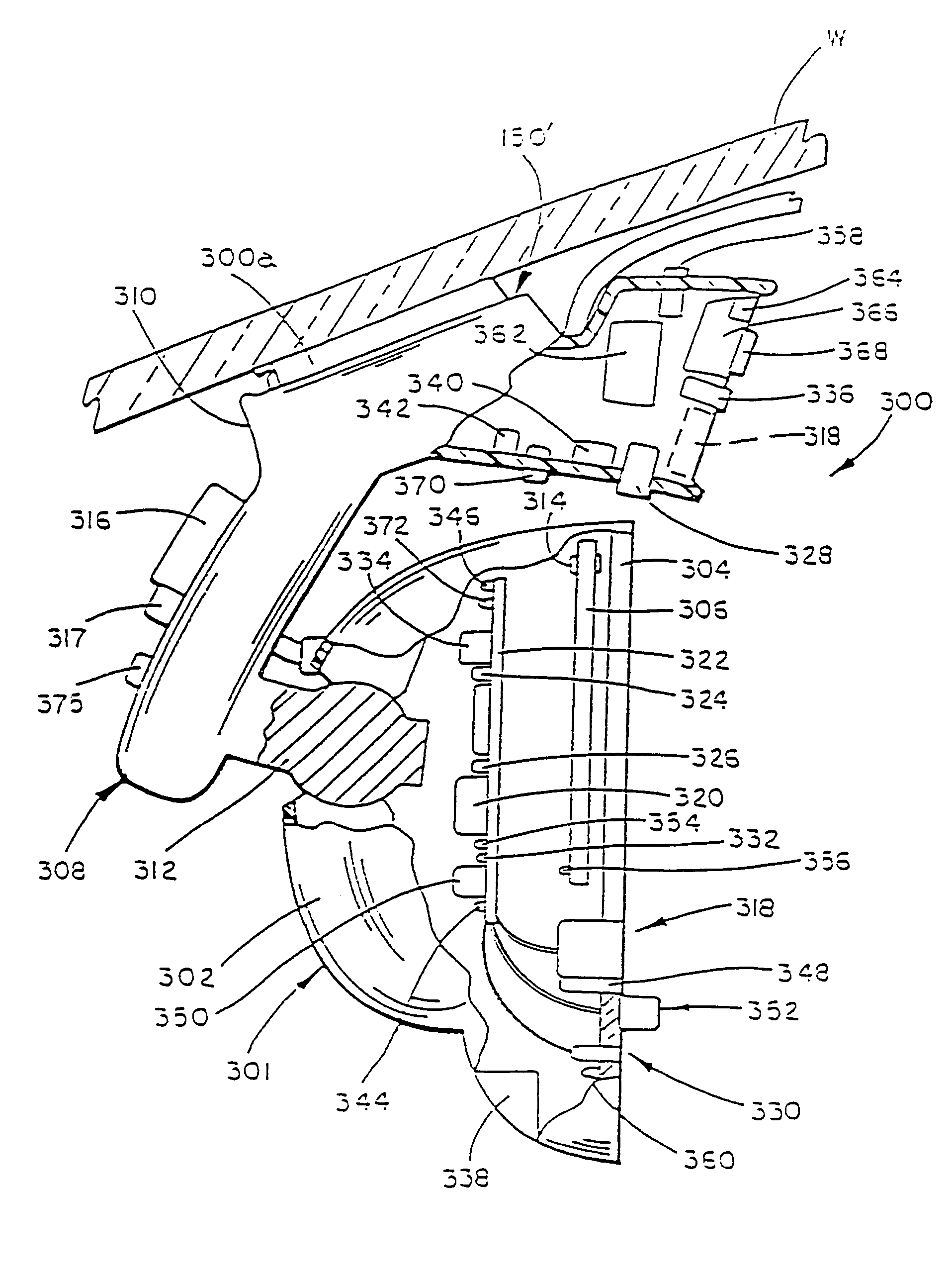
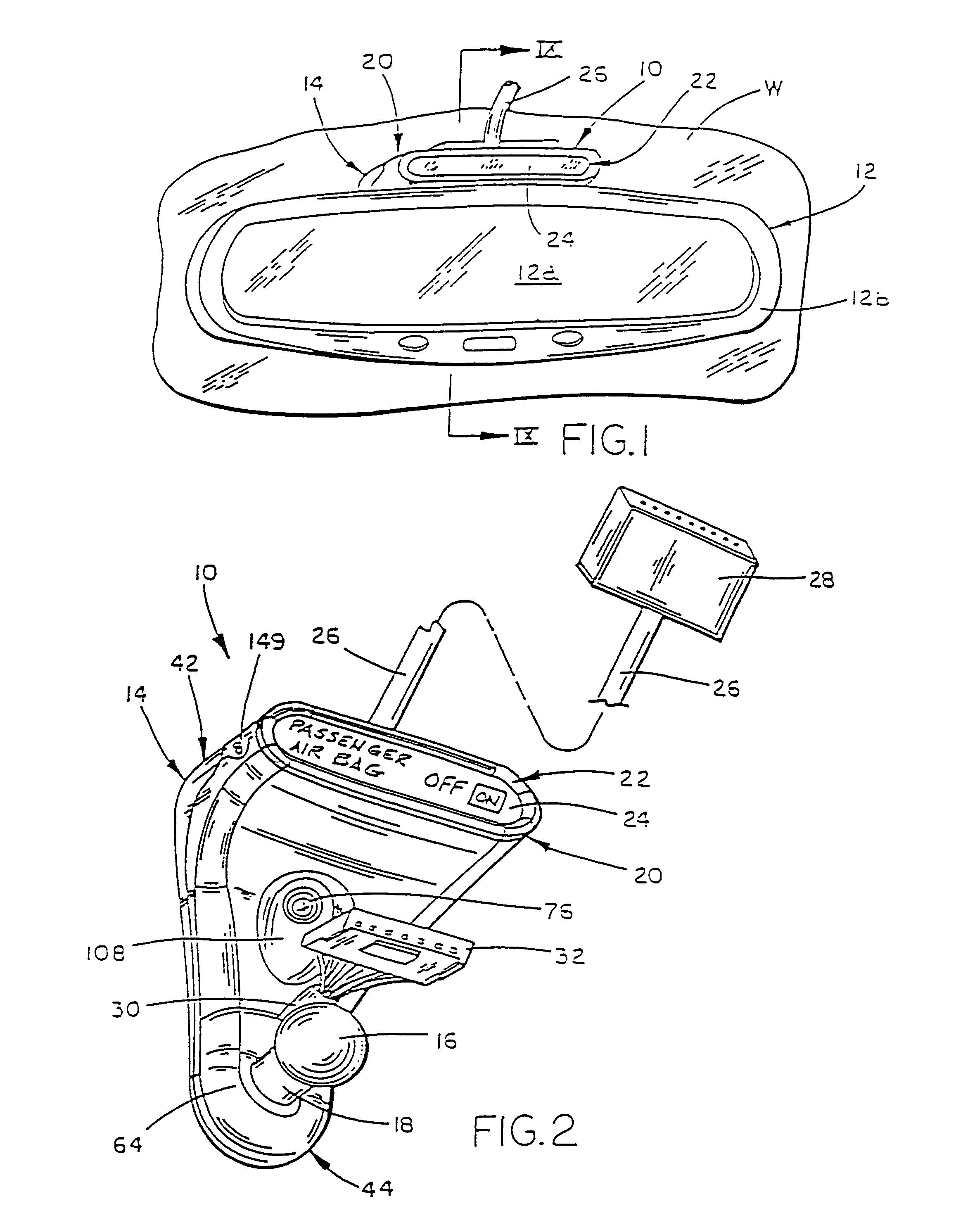
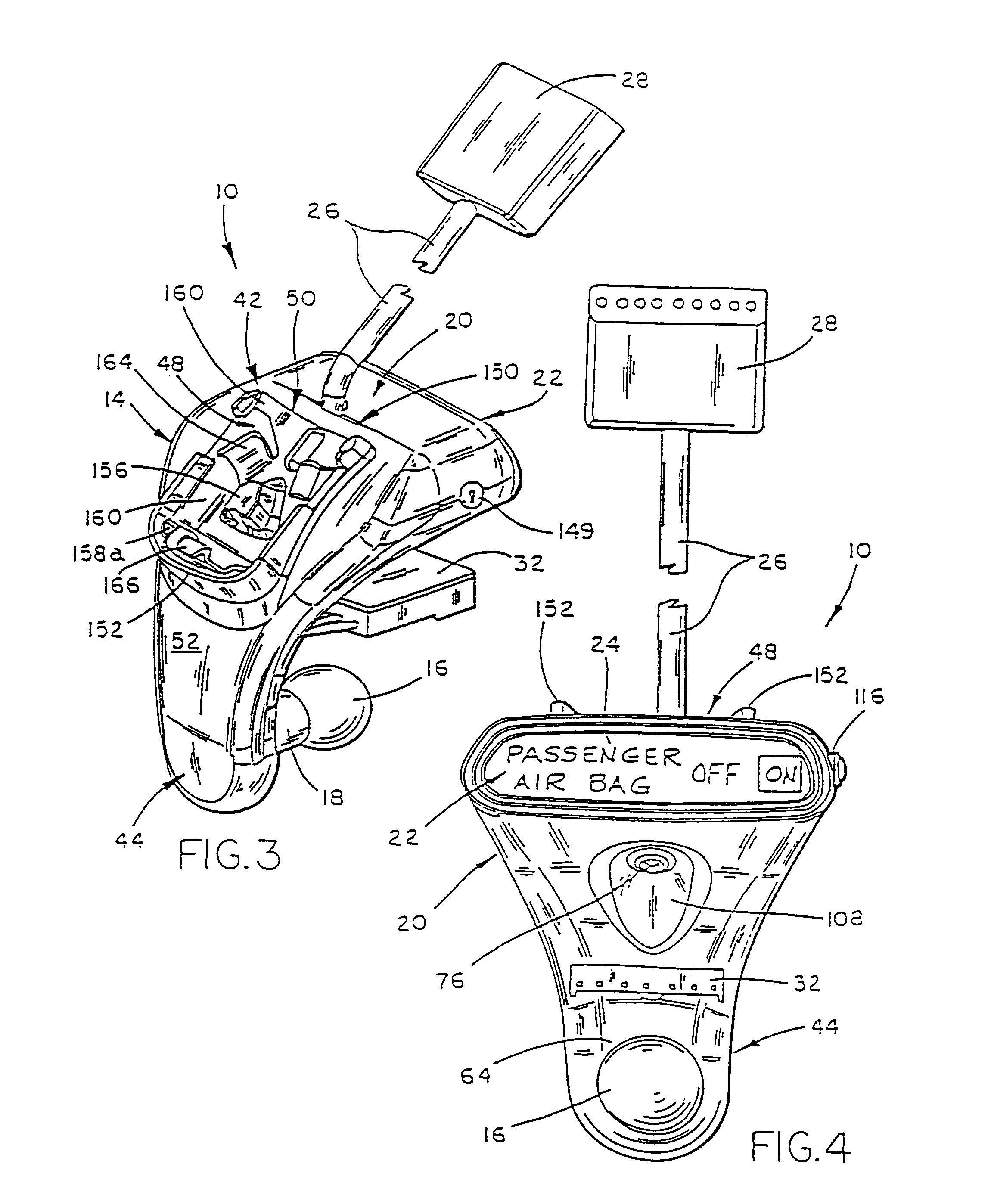
[0057]Referring now to the drawings in greater detail, FIG. 1 illustrates a first embodiment 10 of the unitary rearview mirror support and information display assembly for vehicles of the present invention. Assembly 10 is adapted to be releasably secured or coupled to the front windshield W of a vehicle below the headliner / header section of the interior roof in position for viewing of a rearview mirror 12 supported on assembly 10. Rearview mirror 12 comprises a reflective mirror element 12a housed in a mirror housing 12b. As shown in FIGS. 2–9, assembly 10 includes a rigid mirror stay 14 preferably formed from die cast zinc and an extending, mirror support ball pivot member 16 formed in one piece with the mirror stay on neck 18 at the lower end of the mirror stay. Rearview mirror 12 pivots about ball member 16. A housing 20, preferably having its contour matched to a portion of the mirror stay 14, is preferably removably fitted to the mirror stay, and includes an information display...


PUM


Abstract

An interior rearview mirror system for use in a vehicle includes a mirror support assembly for attachment to the interior of a vehicle. The mirror support assembly comprises a first electronic accessory such as an imaging sensor. A reflective mirror element is disposed in a housing, the housing being pivotally adjustable about the mirror support assembly via a pivot element. The housing includes second and third electronic accessories at least partially controlled by a microprocessor. The mirror support assembly preferably includes a wire passageway for wires passing into the housing for the reflective mirror element. The second and third electronic accessories may be a headlamp controller and automatic dimming circuitry, or may be selected from a variety of other devices such as a garage door opener, an INTERNET interface, a video device, a trip computer, a light, or other items. The mirror assembly may also be in wireless communication with an external device.

Description

CROSS-REFERENCE TO RELATED APPLICATIONS[0001]This application is a continuation of U.S. patent application Ser. No. 10 / 298,194, filed Nov. 15, 2002 now U.S. Pat. No. 6,774,810, entitled REARVIEW MIRROR ASSEMBLY INCORPORATING SUPPLEMENTAL INFLATABLE RESTRAINT SYSTEM STATUS INFORMATION, which is a continuation of Ser. No. 09 / 993,813, filed Nov. 14, 2001, now U.S. Pat. No. 6,483,438, issued Nov. 19, 2002, which is a continuation of Ser. No. 09 / 734,440, filed Dec. 11, 2000, now U.S. Pat. No. 6,366,213, issued Apr. 2, 2002, which is a continuation of Ser. No. 09 / 244,726, filed Feb. 5, 1999, now U.S. Pat. No. 6,172,613, issued Jan. 9, 2001, which is a continuation-in-part of Ser. No. 09 / 025,712, filed Feb. 18, 1998, now U.S. Pat. No. 6,087,953, issued Jul. 11, 2000, the disclosures of which are hereby incorporated by reference herein.FIELD OF THE INVENTION[0002]This invention relates to rearview mirror assemblies, and, more particularly, to a support for an independently adjustable rearvi...

Claims


Application Information

Patent Timeline
Patent Type & Authority Patents(United States)
IPC IPC(8): G08B5/00B60Q1/00B60K35/00B60R1/04B60R1/12B60R21/01B60R21/015
CPCB60K35/00B60R1/04B60R21/01566B60R1/12B60R1/088B60K2350/903B60R2001/1215B60K2370/739
Inventor DELINE, JONATHAN E.LYNAM, NIALL R.
Owner DONNELLY CORP
Why Eureka
Try Eureka