Breast biopsy and needle localization using tomosynthesis systems

a technology of tomosynthesis and biopsy, which is applied in the field of biopsy and needle localization using tomosynthesis system, can solve the problems of less useful x-rays from angles that shadow the gun and stag

Active Publication Date: 2008-02-21
HOLOGIC INC
View PDF34 Cites 180 Cited by
  • Summary
  • Abstract
  • Description
  • Claims
  • Application Information

AI Technical Summary

Benefits of technology

[0003] Tomosynthesis (tomo) is a method of performing three dimensional (3D) breast x-ray imaging. It generates images of cross sectional slices through a compressed breast, and also is used to identify breast pathologies. One of the advantages of tomosynthesis is that the images are three-dimensional, so that once an area of interest is identified in an image, its exact 3D coordinate in the breast can be calculated or estimated, e.g. from the x, y coordinate in the image of a slice and from the z, or depth, coordinate given by the image slice depth location. Another advantage of tomosynthesis is its ability to provide high contrast visibility of objects by the suppression of images from objects at different heights in the breast. Because of its superior contrast visibility, it is expected that there will be pathologies seen on the tomo images that will not be visible using standard x-ray mammography or stereotactic devices or using ultrasound or even MRI or other methods currently employed to provide guidance to the insertion of wires and needles to the location of an identified area of interest. For this reason, it is desired to develop localization methods using tomosynthesis systems that utilize tomosynthesis' natural 3D localization abilities.
[0008] A biopsy system used with a tomosynthesis system can include a needle gun assembly with motorized or non-motorized stage that can direct a needle to a specific 3D coordinate in the breast. This stage may be swung or otherwise moved out of the way of the acquisition system during the initial tomosynthesis scan, so that if desired it does not shadow or interfere with the visualization of the breast or breast area of interest.
[0019] e. Scan angle changes. A larger scan angle than used in conventional tomo imaging can better avoid artifacts from the stage.
[0023] For the pre and post fire images, a facility can be provided to mark the previously identified area of interest location on the current images. This can help visualization of proper needle placement, in case the area of interest becomes harder to see because it has been removed or in case the needle creates large artifacts. The orientation of the needle relative to this mark can provide assurance as to proper location placement.

Problems solved by technology

One challenge arises from the fact that the gun and stage and needle are generally radio-opaque and can contribute artifacts to the images if not properly dealt with.
Lateral access may not have the problem of the gun stage in the field of view, but it can have the needle in the field of view, and there might be other mechanics that if imaged can create image artifacts.
In general, x-rays from angles that shadow the gun and stage are less useful.

Method used


Image

  • Breast biopsy and needle localization using tomosynthesis systems
  • Breast biopsy and needle localization using tomosynthesis systems
  • Breast biopsy and needle localization using tomosynthesis systems

Examples


Embodiment Construction

OF PREFERRED EMBODIMENTS

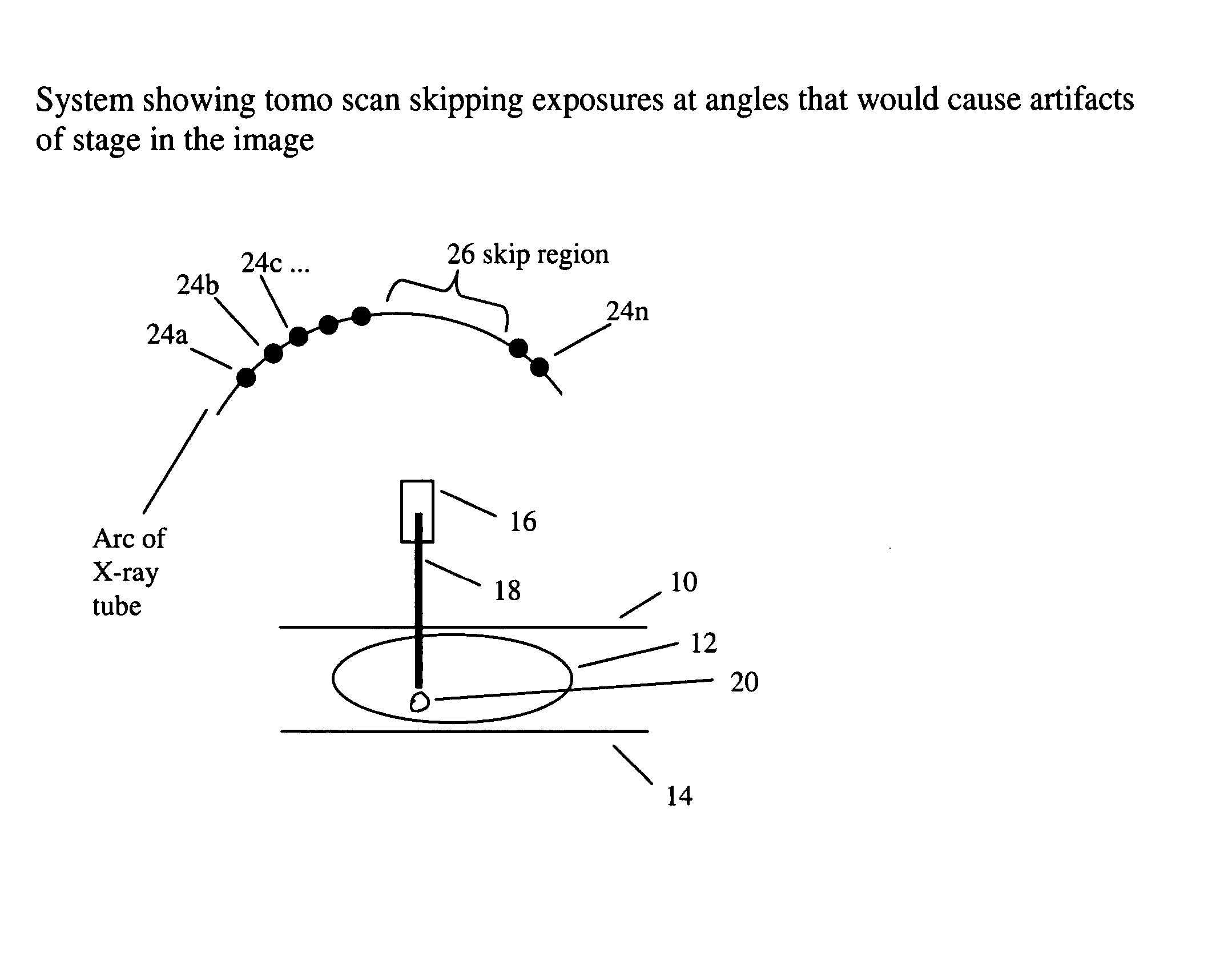
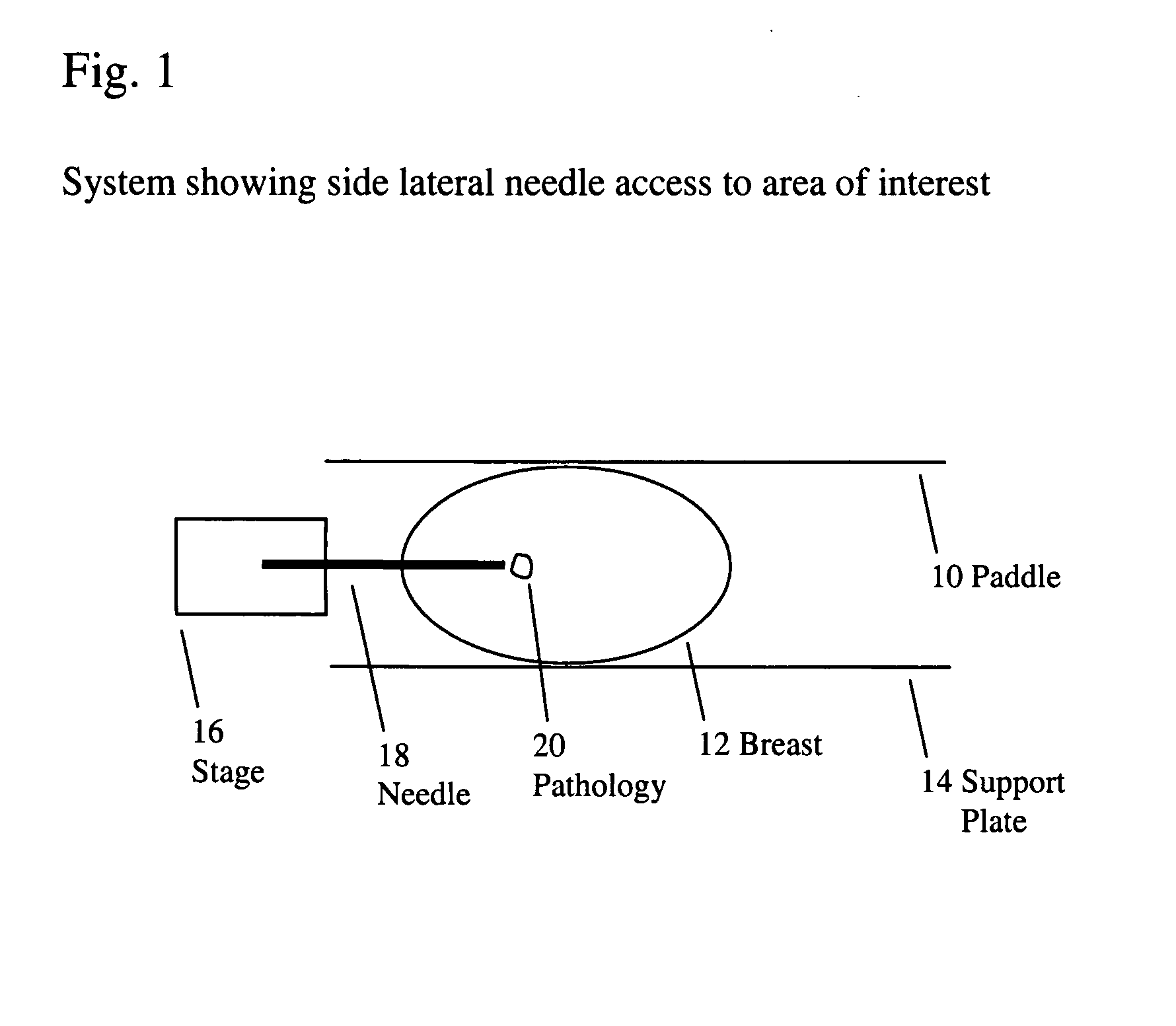
[0028]FIG. 1 illustrates lateral needle access, where a breast compression paddle 10 and a breast support plate 14 can be a part of an otherwise known tomosynthesis system such as described in the co-pending patent applications identified above and incorporated by reference in this patent specification, and a biopsy needle stage 16 and a needle 18 such as used, for example, in the patents identified above that pertain to prone biopsy. For clarity, the rest of the tomosynthesis system and other parts of the biopsy apparatus are not shown in this FIG. 1, and a detailed discussion of the basic aspects of tomosynthesis is not included herein. The reader is referred to the references cited herein for such discussions. For example, image reconstruction can be performed using filtered back projection (for rapid speed of reconstruction) and / or artifact reduction methods (such as ordered statistics back projection), as disclosed, for example, in U.S. Patent Applicatio...


PUM


Abstract

Methods, devices, apparatuses and systems are disclosed for performing mammography, such as utilizing tomosynthesis in combination with breast biopsy.

Description

BACKGROUND AND SUMMARY OF THE DISCLOSURE [0001] Mammography is a well-established method of breast imaging. Using mammograms of the breast, radiologists identify areas suspicious of pathologies. Further identification, such as the determination of cancer is usually done through the taking of a breast biopsy. This is done in several ways. One way is to use mammography to place a wire or needle into the breast, marking the suspected pathology's location. The patient then undergoes an open surgical procedure, and the surgeon can remove tissue from the suspicious area marked by the wire or needle. This is an open surgical biopsy. Another method is known as stereotactic breast biopsy. In this method, using image guidance, a hollow needle is inserted into the breast, and a tissue sample is taken from the area of interest, without a separate surgical procedure. As stated above both methods require some method of localization of the area of interest and a method to direct a wire or needle i...

Claims


Application Information

Patent Timeline
Patent Type & Authority Applications(United States)
IPC IPC(8): A61B6/03
CPCA61B6/025A61B6/0435A61B6/12A61B6/466A61B6/469A61B6/502A61B2019/205A61B2019/5238A61B6/463A61B6/467A61B10/0233A61B19/201A61B10/0275A61B90/17A61B2090/376A61B90/11A61B6/0414A61B6/481A61B6/542A61B10/0041
Inventor DEFREITAS, KENNETH F.SHAW, IAN M.LAVIOLA, JOHNNIKLASON, LOREN THOMASWU, TAOMARK, JOSEPH L.MILLER, MICHAEL E.STEINSMITH, ANDREW P.
Owner HOLOGIC INC
Why Eureka
Try Eureka