Display device and folding portable terminal

a portable terminal and display device technology, applied in the field of portable terminals, can solve the problems of stagnation of the mobile communication market, and achieve the effects of reducing size, high value-added mobile, and high function

Inactive Publication Date: 2005-02-03
SEMICON ENERGY LAB CO LTD
View PDF10 Cites 178 Cited by
  • Summary
  • Abstract
  • Description
  • Claims
  • Application Information

AI Technical Summary

Benefits of technology

The invention having the above-described construction can provide a mobile terminal having a reduced size by using a double-sided display panel having display screens on the front and back, whose display screen can be viewed without opening or closing the mobile terminal. Therefore, a more highly functioned and highly value-added mobile terminal can be provided.
By using a double-sided display panel, a novel design can be achieved, and a highly value-added mobile terminal can be provided. The double-sided display panel can provide display having high viewability from all directions, high contrast ratio and high display quality and is self-luminous. Thus, a light source such as a backlight is not required, and a thin panel can be provided. Therefore, it is especially effective for a mobile terminal.
Furthermore, by using a double-sided display panel including display screens on the front and back, a highly-functioned and highly value-added display device can be provided.

Problems solved by technology

In order to check the internal display screen, the mobile telephone must be opened, which may be inconvenient.
Further, the mobile communication market is apparently stagnating since the number of new subscriptions to mobile telephone services is continuously decreasing.

Method used


Image

  • Display device and folding portable terminal
  • Display device and folding portable terminal
  • Display device and folding portable terminal

Examples


embodiment 1

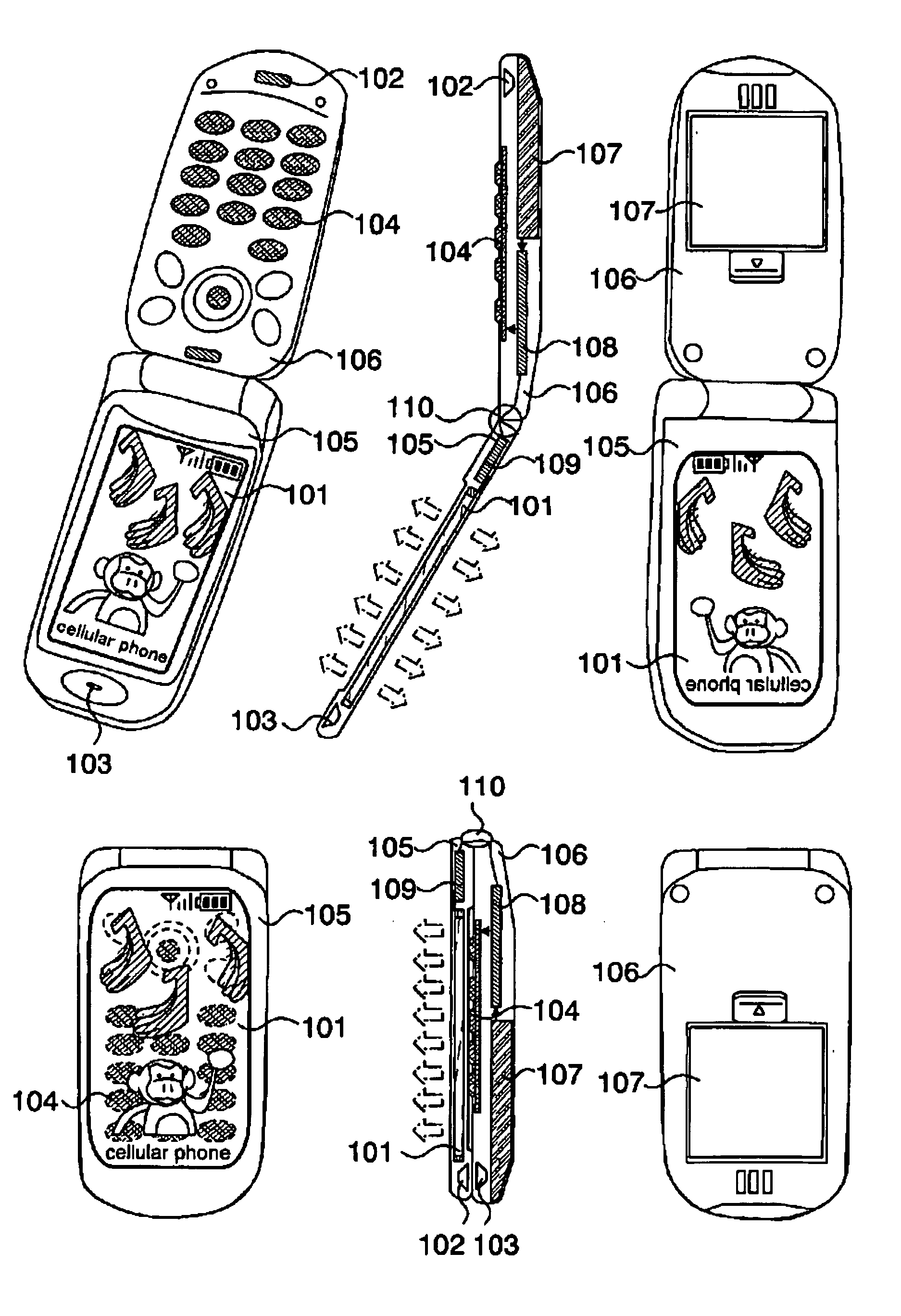
A detail construction of a mobile telephone according to a first embodiment as a mobile terminal to which the invention is applied will be described with reference to FIG. 1. FIGS. 1(A) to (F) include a double-sided display panel 101, a speaker 102 functioning as a receiver, a microphone 103 functioning as a transmitter, operation buttons 104 for operating the terminal, a first housing 105, a second housing 106, a battery 107 functioning as a power supply, a module 108 including an IC for driving the terminal, a module 109 for driving the double-sided display panel 101 and a hinge 110 for connecting the first housing 105 and the second housing 106 foldably. The terminal may include a camera having a shooting function and an antenna for receiving electromagnetic waves, which are not shown. The terminal may further include accessories such as a strap, an earphone / microphone and a stereo earphone set.

The invention is characterized in that the double-sided display panel 101 and the m...

embodiment 2

An embodiment of the invention will be described with drawings. A construction of a double-sided display panel 101 having first and second display screens according to this embodiment will be described in detail. FIG. 3(A) shows an active type using a transistor, and FIG. 3(B) shows a passive type.

In FIG. 3(A), a drive transistor 201, a first electrode (pixel electrode) 202, a light-emitting layer 203 and a second electrode (opposed electrode) 204 are provided over a substrate 200 having a translucency. A laminate of the first electrode 202, light emitting layer 203 and second electrode 204 corresponds to a light emitting element 225. The invention is characterized in that the first electrode 202 and second electrode 204 contain a material having a translucency. Thus, the light emitting element 225 emits light in a first direction toward the substrate 200 and in a second direction, which is opposite of the first direction, and has a first display area 205 and a second display are...

embodiment 3

An embodiment of the invention will be described with reference to drawings. A construction of a double-sided display panel 101 having first and second display screens and further having an image sensor function according to this embodiment will be described in detail.

In FIG. 4(A), a drive transistor 201, a first electrode (pixel electrode) 202 containing a material having a translucency, a light-emitting layer 203 and a second electrode (opposed electrode) 204 containing a material having a translucency are provided over a substrate 200 having a translucency. A light emitting element 225 emits light in a first direction toward the substrate 200 and in a second direction, which is opposite of the first direction. An optoelectronic transducer 238 including a laminate of a P-type layer 231, an I-type (intrinsic) layer 232 and an N-type layer 233, an electrode 230 connecting to the P-type layer 231 and an electrode 234 connecting to the N-type layer 233 are provided over an insulati...


PUM


Abstract

It is an object to provide a highly functioned and highly value-added display device and mobile terminal. It is another object to provide a display device and mobile terminal characterized by including a plurality of pixels arranged in a matrix form and a first display screen over one surface of a substrate having a translucency, a second display screen over the opposite surface of the one surface of the substrate, each of the plurality of pixels having a light emitting element for emitting light toward the first display screen and the second display screen, and a first polarizer over one surface of the substrate and a second polarizer over the opposite surface of the one surface of the substrate.

Description

TECHNICAL FIELD The invention relates to a portable terminal such as a mobile telephone and a personal digital assistant (PDA), and more specifically, it relates to a mobile terminal including a light emitting element and having a double-sided display panel having display screens on the front and back. The invention further relates to a display device having display screens on the front and back. The invention further relates to a display device having an image sensor function and having display screens on the front and back. BACKGROUND ART In recent years, instead of a liquid crystal display (LCD) having pixels using liquid crystal elements, a light-emitting apparatus using a light emitting element typically such as an electro-luminescence (EL) element has been studied and developed as a light-emitting apparatus. The light-emitting apparatus is widely used as a display screen of a mobile terminal by taking advantage of high quality and wide viewing angles based on the light-emit...

Claims


Application Information

Patent Timeline
Patent Type & Authority Applications(United States)
IPC IPC(8): G06F1/16G06F3/14H01L27/32H01L51/52H04M1/02H04M1/724
CPCG06F1/1616H04M2250/16G06F1/1647G06F1/1677G06F1/1686G06F3/1423G06F2200/1614G09G2300/023G09G2340/0492H01L27/3209H01L27/3234H01L27/3267H01L51/5262H01L51/5281H01L2251/5323H01L2251/558H04M1/0214H04M1/0245H04M1/72519G06F1/1637H04M1/724H10K59/32H10K59/65H10K59/128H10K50/85H10K50/86H10K2102/3031H10K2102/351H05B33/14G09F9/40H04M1/00G09G5/00
Inventor YAMAZAKI, SHUNPEIARAI, YASUYUKIWATANABE, YASUKOANZAI, AYAGODO, HIROMICHISAKATA, JUNICHIROTSUCHIYA, KAORU
Owner SEMICON ENERGY LAB CO LTD
Why Eureka
Try Eureka