Column-stabilized offshore platform with water-entrapment plates and asymmetric mooring system for support of offshore wind turbines

a technology of asymmetric mooring system and offshore platform, which is applied in the direction of wind motor with parallel air flow, wind energy generation, vessel movement reduction by foil, etc., can solve the problems of relatively heavy structure and less economically feasible, and achieve the effect of improving the performance of the wind turbine platform, facilitating the production of a structure, and light weigh

Active Publication Date: 2011-02-17
PRINCIPLE POWER
View PDF5 Cites 176 Cited by
  • Summary
  • Abstract
  • Description
  • Claims
  • Application Information

AI Technical Summary

Benefits of technology

[0007]Semi-submersible offshore floating wind turbine platforms that include at least three columns are described herein. In addition to at least three columns, the wind turbine platforms described herein include additional features that improve the performance of the wind turbine platform. In an embodiment represented in FIG. 6, the floating wind turbine platform includes an active ballast system that moves water ballast between the columns to keep the tower vertically aligned. Moreover, an alignment sensor can be coupled to the platform to determine the wind loading. Even further, wind turbine platform according to the present description may include one or more additional features, such as an asymmetric mooring system and an active ballast system that facilitate production of a structure that can not only withstand environmental loads, but is also relatively light weight when compared to other platform designs and can lead to better economics for energy production.

Problems solved by technology

In contrast, in some previous designs where the tower is positioned at the center of the deck, the structure is relatively heavy and potentially less economically feasible because, due to the weight of the tower and turbine and the aerodynamic moment, the structure must support large loads at the middle of a long structure.

Method used


Image

  • Column-stabilized offshore platform with water-entrapment plates and asymmetric mooring system for support of offshore wind turbines
  • Column-stabilized offshore platform with water-entrapment plates and asymmetric mooring system for support of offshore wind turbines
  • Column-stabilized offshore platform with water-entrapment plates and asymmetric mooring system for support of offshore wind turbines

Examples


Embodiment Construction

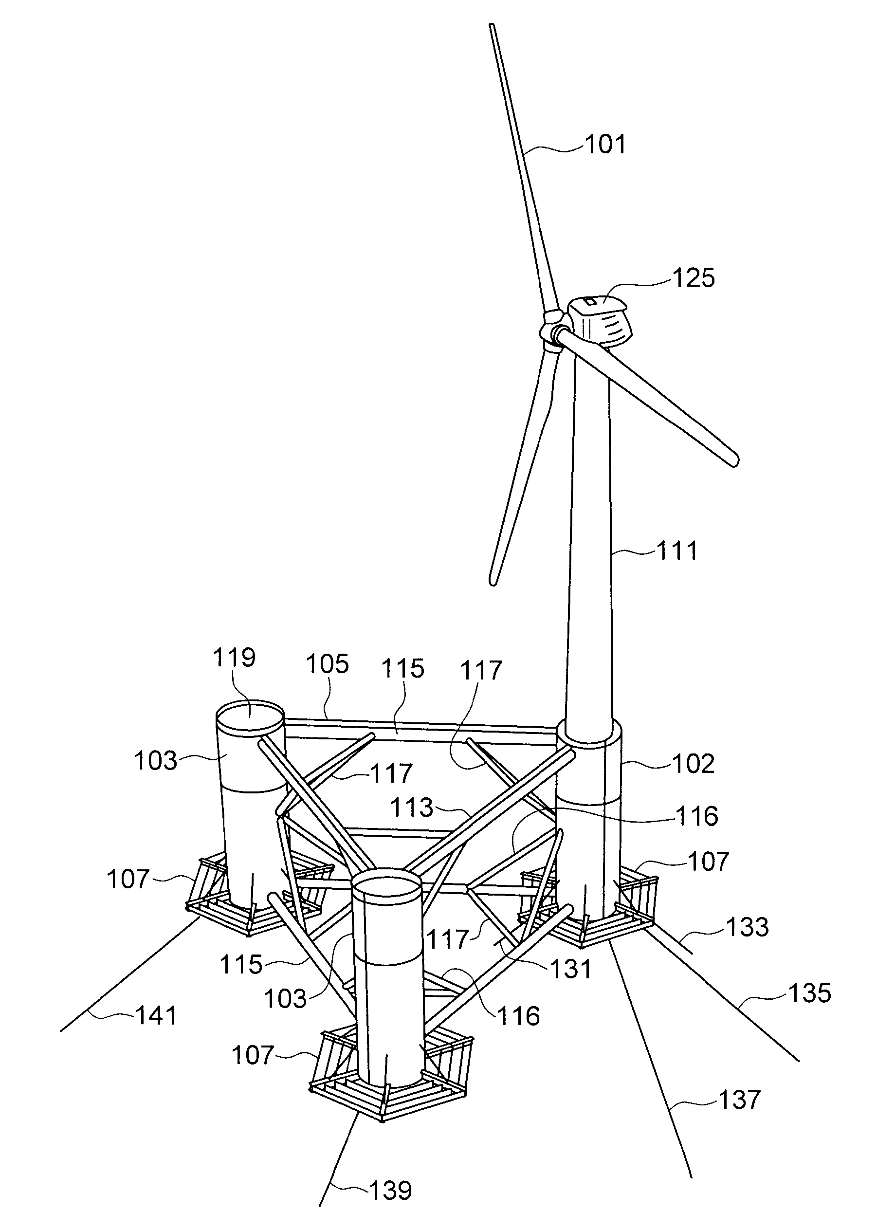
[0040]Semi-submersible, floating wind turbine platforms are described herein. The platforms described herein can be used, for example, in offshore wind turbine installations. With reference to FIG. 6, wind turbine system according to the present description can include an offshore platform 105 having at least three columns 102, 103. A planar water-entrapment plate 107 is attached to the bottom portion of each column 102, 103. In an embodiment, the columns 102, 103 are cylindrical in shape. However, the columns can be configured in any shape suitable for constructing a wind turbine platform. A wind turbine tower 111 is positioned directly above a stabilizing column 102. The two independent stabilizing columns 103 that do not support the turbine tower 111 are separated by an angle that can range from about 40 to 90 degrees from the tower supporting column 102. While the platform 105 shown in the illustrations includes three columns 102, 103, in other embodiments, the platform can incl...


PUM


Abstract

A floating wind turbine platform includes a floatation frame (105) that includes three columns (102, 103) that are coupled to each other with horizontal main beams (115). A wind turbine tower (111) is mounted above a tower support column (102) to simplify the system construction and improve the structural strength. The turbine blades (101) are coupled to a nacelle (125) that rotates on top of the tower (111). The turbine's gearbox generator and other electrical gear can be mounted either traditionally in the nacelle, or lower in the tower (111) or in the top of the tower-supporting column (102). The floatation frame (105) includes a water ballasting system that pumps water between the columns (102, 103) to keep the tower (111) in a 10 vertical alignment regardless of the wind speed. Water-entrapment plates (107) are mounted to the bottoms of the columns (102, 103) to minimize the rotational movement of the floatation frame (105) due to waves.

Description

CROSS REFERENCE TO RELATED APPLICATIONS[0001]This patent application claims priority to U.S. Provisional Patent Application No. 61 / 125,241, titled “Column-Stabilized Offshore Platform With Water-Entrapment Plates And Asymmetric Mooring System For Support Of Offshore Wind Turbines” filed Apr. 23, 2008, the entire contents of which are hereby incorporated by reference.BACKGROUND[0002]A wind turbine is a rotating machine which converts the kinetic energy from the wind into mechanical energy that is then converted to electricity. Wind turbines have been developed for land based installations as well as offshore installations. The land based wind turbines are fixed to the ground and located in windy areas. There are vertical axis wind turbines that have the main rotor shaft arranged vertically and horizontal axis wind turbines that have a horizontal rotor shaft that is pointed into the wind. Horizontal axis wind turbines generally have a tower and an electrical generator coupled to the t...

Claims


Application Information

Patent Timeline
Patent Type & Authority Applications(United States)
IPC IPC(8): H02P9/04F03D9/00E02D5/74E02B17/02
CPCB63B35/44E04H2012/006E02B9/00E02B2017/0091F03D1/001F03D11/04F05B2240/93F05B2240/95Y02E10/22Y02E10/727B63B21/50B63B39/02B63B39/04F03D7/0204F03D9/002B63B2039/067B63B39/03F03D13/25B63B35/00F03D9/25F03D13/10B63B1/107F03D9/257F03D80/00F03D17/00B63B39/06B63B2035/446Y02E10/20Y02E10/72E02B17/04
Inventor RODDIER, DOMINIQUECERMELLI, CHRISTIAN
Owner PRINCIPLE POWER
Why Eureka
Try Eureka