Method for preparing cryomilled aluminum alloys and components extruded and forged therefrom

a technology of aluminum alloys and components, which is applied in cryogenics, metal-working apparatuses, transportation and packaging, etc., can solve the problems of reducing the usefulness of aluminum and titanium alloys. , to achieve the effect of high capacity, high strength and maintaining or improving strength

Inactive Publication Date: 2005-06-07
THE BOEING CO
View PDF22 Cites 174 Cited by
  • Summary
  • Abstract
  • Description
  • Claims
  • Application Information

AI Technical Summary

Benefits of technology

[0015]Cryomilling the aluminum and secondary metal in accordance with this invention provides a resultant metallic powder having a very stable grain structure. The average grain size within the alloy is less than 0.5 μm, and alloys with average grain size less than 0.1 μm may be produced. The small, stable grains of the alloy allow components to be extruded or forged from the alloy which exhibit significantly improved strength over similar alloys produced by other methods. The cryomilled aluminum alloys also exhibit dramatically improved strength at low temperatures.
[0022]The physical properties of the alloy are present within the invented alloy powder produced in accordance with the invention. The extraordinary strength and the ability of the alloy to maintain high strength at extremely low temperatures are believed to be due to the unique grain structure, grain size, and interaction of constituents of the alloy caused by the cryomilling process. The improved physical properties of the alloy are exhibited when the alloy powder is compressed and extruded into a solid metal component. The metal components produced from the powder have an extremely high yield strength, between about 73 ksi and about 104 ksi, and ultimate tensile strength, between about 78 ksi and about 107 ksi. More importantly, the metal alloys have the same or higher yield strength at low temperatures, ranging from about 67 ksi to about 126 ksi at −320° F., and ranging from about 78 ksi to about 106 ksi at −423° F. Similarly, the ultimate tensile strength of the alloys ranges from about 78 ksi to about 129 ksi at −320° F. and from about 107 ksi to about 121 ksi at −423° F.
[0023]The invented alloys produced with the invented method therefore permit the production of high strength components which have maintained or improved strength at very low temperatures. The high strength alloys are well suited for use within liquid fuel rocket motors, particularly as turbopump impellers and propellant ducts for reusable launch vehicles. Components extruded or forged from the alloys are light weight, but are able to resist the extreme forces and extremely low temperatures experienced within the rocket engine. Thus, by utilizing the components formed from the invented alloy, higher capacity, low weight rocket engines may now be constructed.

Problems solved by technology

However, as the performance demands of the industry have increased, previously known aluminum and titanium alloys have been pushed to the limits of their usefulness.
The operation of high performance rocket propulsion systems are particularly demanding on metallic components.
The heat treated aluminum parts remain adequate for most modem day propulsion systems but fall short of meeting the demands of today's high-performance rocket engines and other similarly demanding propulsion systems.
The components formed by precipitation heat treatment are not particularly suited for use in extremely cold environments such as those temperatures found in liquid fuel rocket engines.
Further, heat treatment introduces residual stress and distortion in the metallic components, which is particularly troublesome in thin-walled or high-precision components.
Although considerable research has occurred regarding different types of oxide dispersions and methods by which oxide, nitride, and other precipitates are dispersed within aluminum alloys, the improvement in the strength of the dispersion strengthened alloys over the heat treated alloys of the past is fairly modest.
Furthermore, the dispersion-strengthened aluminum alloys are designed for use at high temperatures, and are not particularly suited for use in extremely low temperature environments.
The aluminum components must be capable of continual high-speed operation, typically below −300° F. Existing heat treated and dispersion strengthened aluminum alloys are unable to meet the demands of the next generation of rocket motors and their high stress, extremely low temperature environments.

Method used


Image

  • Method for preparing cryomilled aluminum alloys and components extruded and forged therefrom
  • Method for preparing cryomilled aluminum alloys and components extruded and forged therefrom
  • Method for preparing cryomilled aluminum alloys and components extruded and forged therefrom

Examples


example 1

Production of Aluminum / Magnesium Alloy

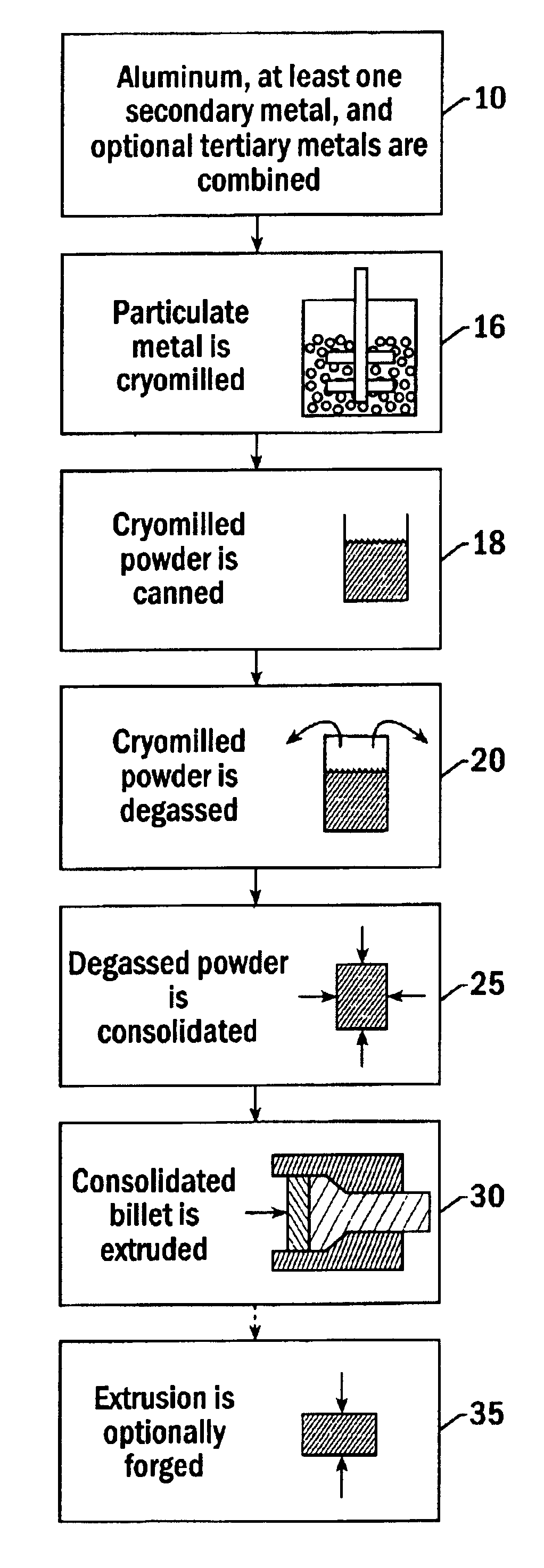
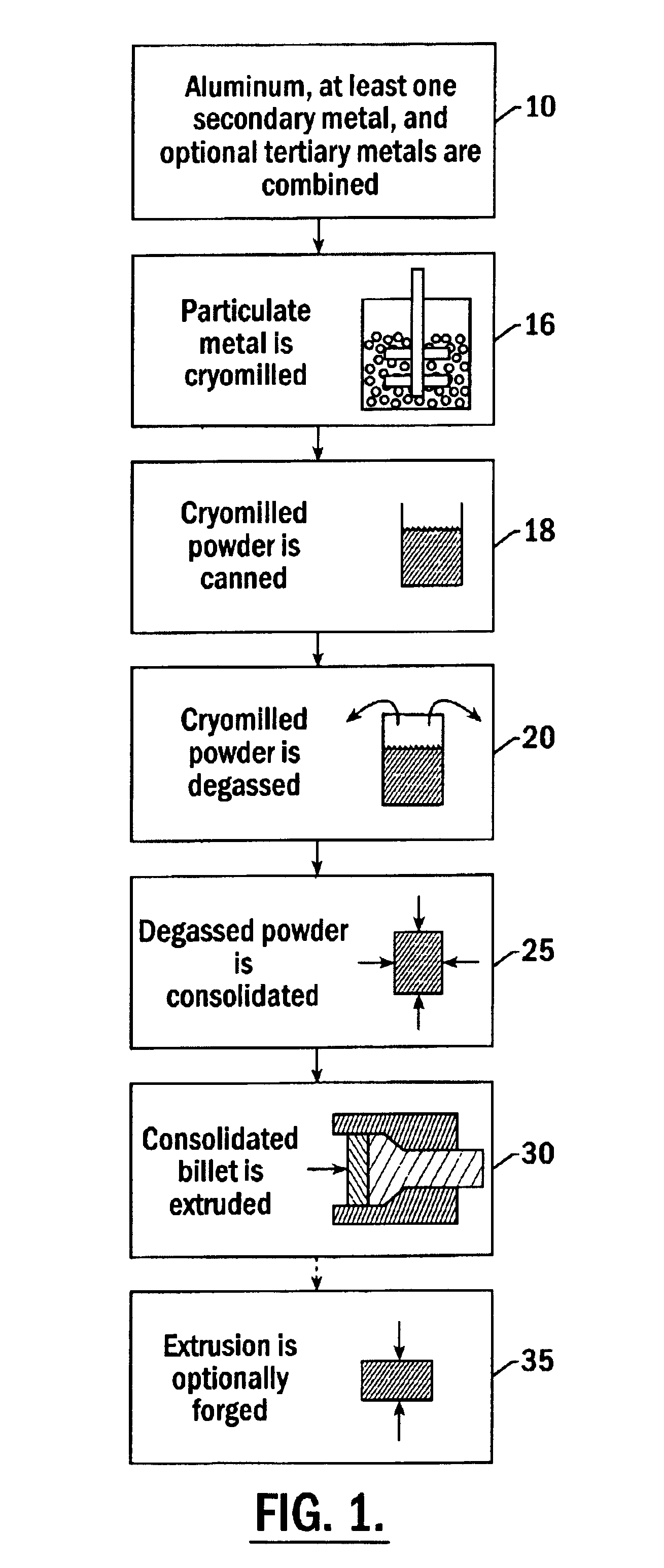
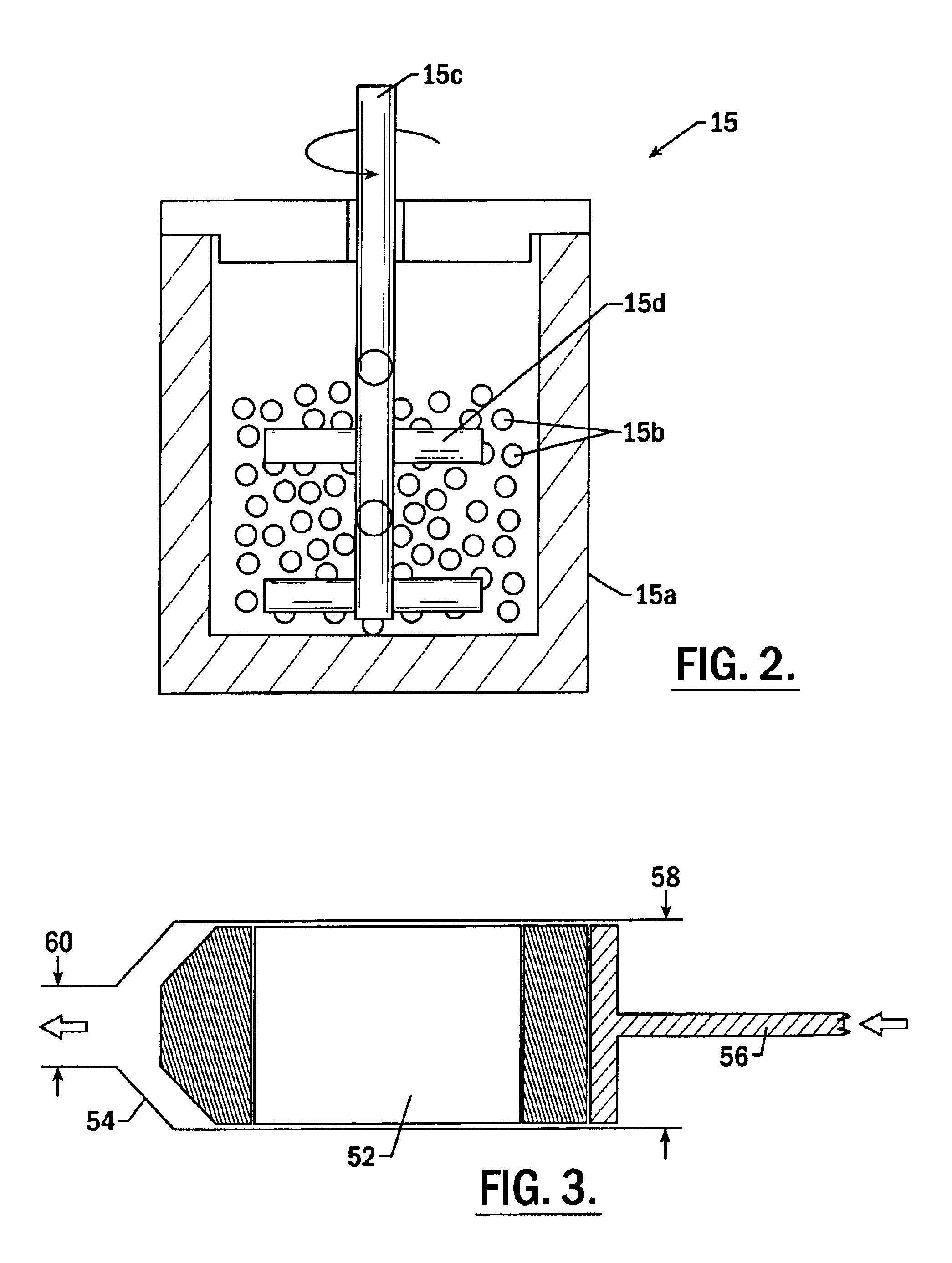
[0066]Aluminum alloy powders of composition 6.7 wt % Mg+Al (balance) were cryomilled, canned, degassed, consolidated, and extruded into a 3″ diameter bar. Cryomilling was carried out as follows. The attritor was filled with 640 kg grams of 0.25 inch diameter steel balls. Liquid nitrogen was flowed into the attritor. Flow was maintained for at least about one hour to cool the balls and attritor until the rate of boil off was sufficiently low to allow the balls to become completely submerged in the liquid nitrogen. A transfer hopper was loaded with 17445 grams of aluminum powder, 2555 grams of 50 wt % aluminum 50 wt % magnesium powder, and 40 grams of stearic acid. Loading of the hopper was carried out in a glove box under dry nitrogen purge. These components were transferred from the hopper into the attritor by draining from the hopper into a tube inserted through the lid of the attritor vessel. The attritor arms were then rotated in brief pulses...

example 2

Production of Aluminum / Magnesium Alloy

[0070]Aluminum alloy powders of composition 8.5 wt % Mg+Al (balance) were cryomilled, canned, degassed, consolidated and extruded into a 3″ diameter tube, wall thickness 0.25″ as described in Example 1. In this case, the extrusion area ratio was 23:1, the ram speed was 0.02 inches per second, and the average strain rate was 0.055 sec−1. The extrusion had the tensile properties shown in Table III. The extruded tube exhibited physical properties that were superior to those of tubes having similar metallic components produced by traditional methods.

[0071]

TABLE IIIσy (ksi)σu (ksi)elong. (%)R.A. (%)   70 F. - long.73.478.314.231.5   70 F. - trans.71.477.56.713.6−320 F. - long.85.891.612.216.1−320 F. - trans.85.689.47.010.9

example 3

Production of Al / Mg / Zn / Cu / Co Alloy

[0072]Aluminum alloy powders of composition 2.5 wt % Mg+8.0 wt % Zn+1.0 wt % Cu+1.4 wt % Co+Al (balance) (composition similar to AA7090) were cryomilled, canned, degassed, consolidated and extruded into a 0.4″ diameter extrusion according to the method of Example 1. The extrusion had the longitudinal tensile properties shown in Table IV, which are superior to those corresponding alloys which were not treated in accordance to the invented method.

[0073]

TABLE IVσy (ksi)σu (ksi)elong. (%)R.A. (%)   70 F.104.81076.37−320 F.126.8129.11.84.7


PUM

PropertyMeasurementUnit
weight %aaaaaaaaaa
temperatureaaaaaaaaaa

Abstract

High strength aluminum alloy powders, extrusions, and forgings are provided in which the aluminum alloys exhibit high strength at atmospheric temperatures and maintain high strength and ductility at extremely low temperatures. The alloy is produced by blending about 89 atomic % to 99 atomic % aluminum, 1 atomic % to 11 atomic % of a secondary metal selected from the group consisting of magnesium, lithium, silicon, titanium, zirconium, and combinations thereof, and up to about 10 atomic % of a tertiary metal selected from the group consisting of Be, Ca, Sr, Ba, Ra, Sc, V, Cr, Mn, Fe, Co, Ni, Cu, Zn, Y, Nb, Mo, Tc, Ru, Rh, Pd, Ag, Cd, W, and combinations thereof. The alloy is produced by nanostructure material synthesis, such as cryomilling, in the absence of refractory dispersoids. The synthesized alloy is then canned, degassed, consolidated, extruded, and optionally forged into a solid metallic component. Grain size within the alloy is less than 0.5 μm, and alloys with grain size less than 0.1 μm may be produced.

Description

FIELD OF THE INVENTION[0001]The present invention relates to the production of high strength cryomilled aluminum alloys, and to the extrusion and forging of cryomilled aluminum alloys.BACKGROUND OF THE INVENTION[0002]The aerospace industry requires structural metals and alloys that provide maximum strength with minimum weight. Traditionally, these roles have been fulfilled by aluminum, titanium, and alloys thereof. However, as the performance demands of the industry have increased, previously known aluminum and titanium alloys have been pushed to the limits of their usefulness.[0003]The operation of high performance rocket propulsion systems are particularly demanding on metallic components. Extruded and forged parts such as fuel turbopump impellers and other rotational components require high strength and low density, but also require adequate ductility and toughness. Furthermore, because the rotational components of liquid-fueled rocket engines are exposed to cryogenic liquids at ...

Claims


Application Information

Patent Timeline
Patent Type & Authority Patents(United States)
IPC IPC(8): B22F9/04B22F9/02C22C1/04
CPCB22F9/04C22F1/053C22F1/047C22C30/00C22C21/10C22C21/06C22C1/0416B22F3/1208B22F3/15B22F3/20B22F1/0044B22F2009/041B22F2999/00B22F2998/10B22F2202/03B22F1/07
Inventor FRITZEMEIER, LESLIE G.MATEJCZYK, DANIEL E.VAN DAAM, THOMAS J.
Owner THE BOEING CO
Why Eureka
Try Eureka