Power control unit

a technology of power control unit and power control device, which is applied in the direction of secondary cell servicing/maintenance, instruments, transportation and packaging, etc., to achieve the effect of suppressing trouble, preventing trouble, and prolonging the service life of storage means

Inactive Publication Date: 2006-01-19
HITACHI LTD
View PDF5 Cites 19 Cited by
  • Summary
  • Abstract
  • Description
  • Claims
  • Application Information

AI Technical Summary

Benefits of technology

[0017] The technologies of Patent Documents 1 and 2 are designed to disconnect the storage means from the power control circuit only after the storage means has a trouble instead of controlling charging and discharging of the storage means to prevent troubles from occurring in the storage means. It is possible to make the service life of the storage means longer by controlling charging and discharging of the storage means to suppress occurrence of troubles.
[0018] Therefore, it has been hoped that a power control apparatus be actualized that can control charging and discharging of storage means to suppress occurrence of troubles while enabling quick charging and reduction of the capacity relative to the discharging current.
[0021] Accordingly, an object of the present invention is to provide a power control apparatus that can control charging and discharging of storage means to suppress the occurrence of a trouble in the storage means while accomplishing quick charging and reduction of battery capacities relative to discharging currents.
[0039] In summary, the present invention can provide a power control apparatus that can control charging and discharging of storage means to suppress the occurrence of a trouble in the storage means while accomplishing quick charging and reduction of battery capacities relative to discharging currents.

Problems solved by technology

However, the prior arts disclosed by Patent Documents 1 and 2 cannot charge or discharge currents for “n” batteries in a system having “n” sets of parallel-connected storage means each of which contains a plurality of series-connected batteries and cannot increase the input / output (current) further.

Method used


Image

  • Power control unit
  • Power control unit
  • Power control unit

Examples


first embodiment

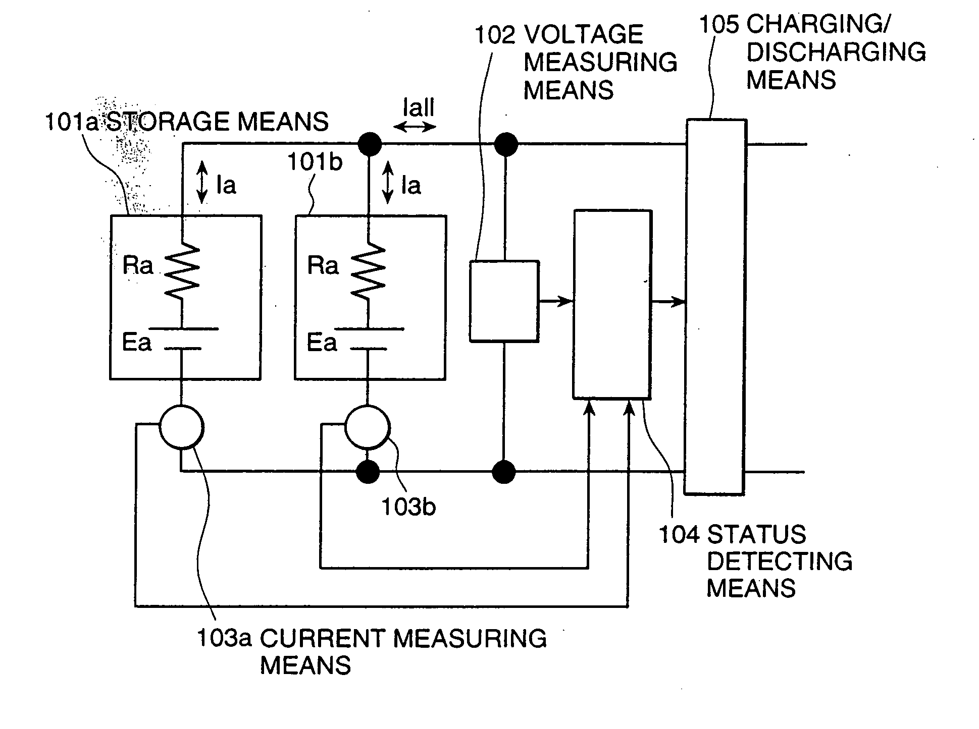
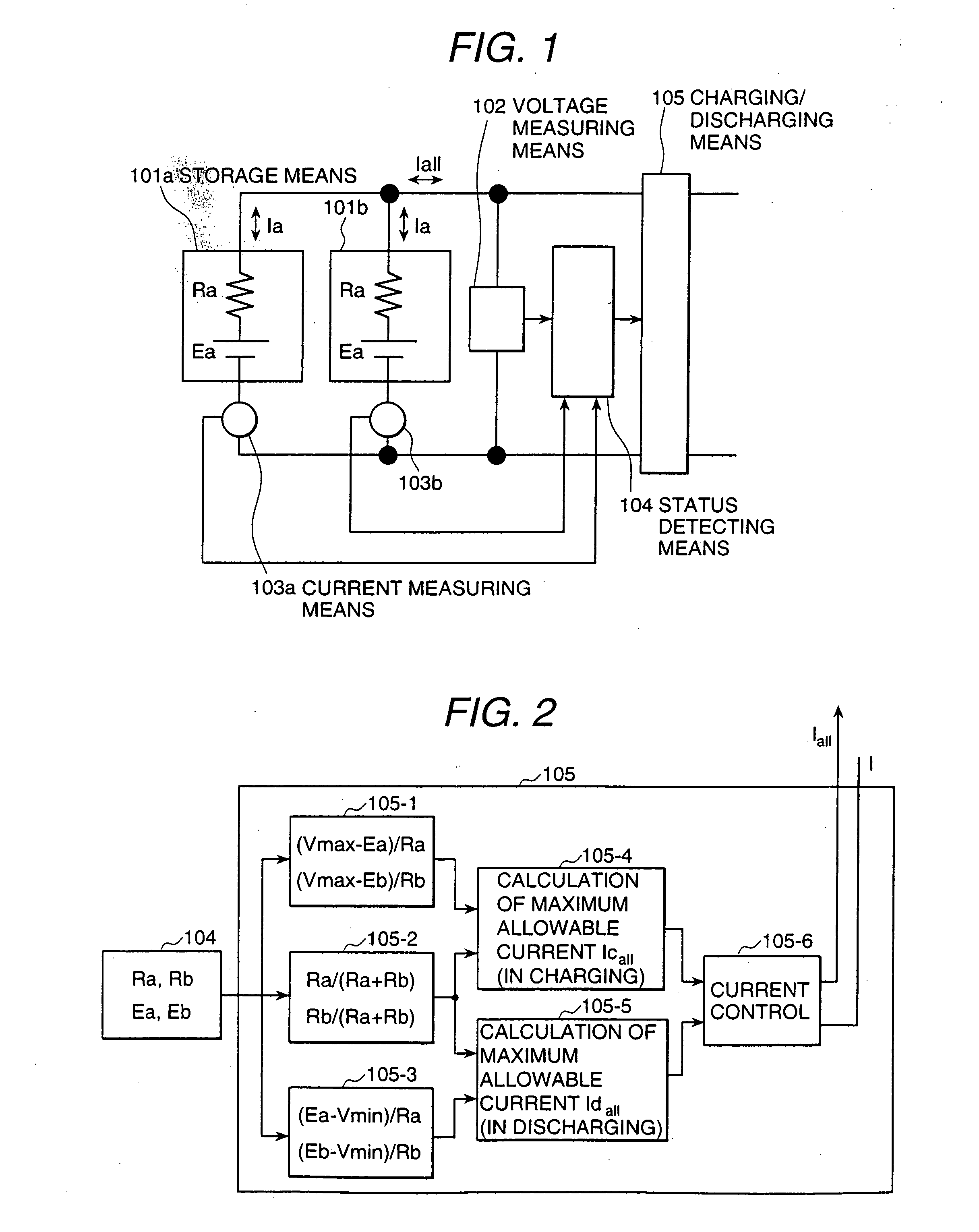
[0053]FIG. 1 is a schematic diagram of a power control apparatus which is the invention. This embodiment is an example of applying the present invention to a power supply charging / discharging controlling means.

[0054] In FIG. 1, means 101a and 101b are power storage means. A means 101b is a voltage measuring means. Means 103a and 103b are current measuring means. A means 104 is a status detecting means and a means 105 is a charging / discharging controlling means.

[0055] A current measuring means 103a is connected in series to a storage means 101a and a current measuring means 103b is connected in series to a storage means 101b. The series set of the current measuring means 103a and the storage means 101a is connected in parallel with the other series set of the current measuring means 103b and the storage means 101b.

[0056] A voltage measuring means 102 is connected in parallel with these parallel sets of the current measuring means 103 and the storage means 101. Further, a charging / d...

second embodiment

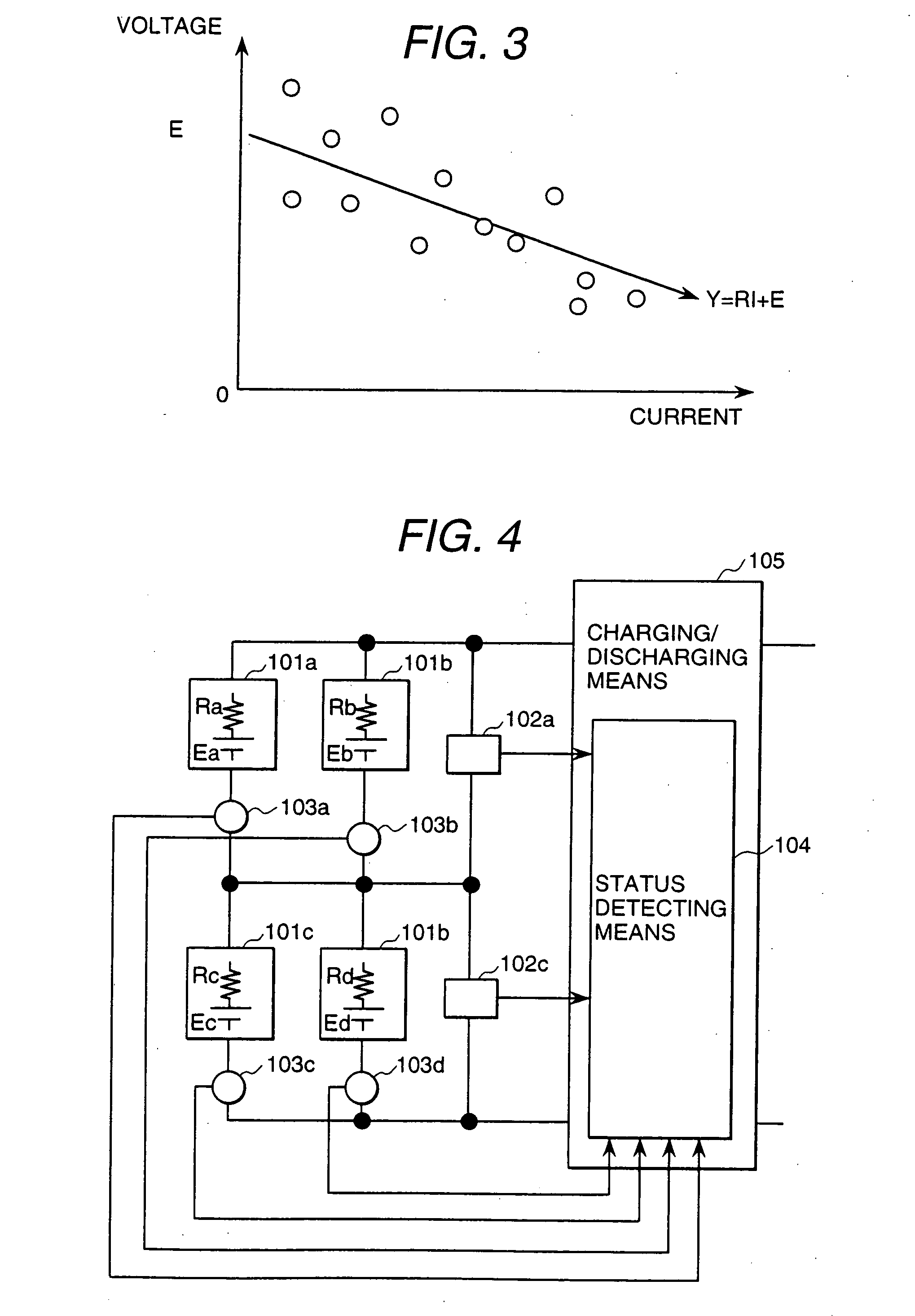
[0096]FIG. 4 is a schematic diagram of a power control apparatus which is the invention. This embodiment is an example of applying the invention to a power charging / discharging controlling means.

[0097] In FIG. 4, a storage means 101a and a current measuring means 103a are connected in series to each other. A storage means 101b and a current measuring means 103b are connected in series to each other. A voltage measuring means 102a is connected in parallel to these series sets of a storage means and a current measuring means.

[0098] Similarly, a storage means 101c and a current measuring means 103c are connected in series to each other. A storage means 101d and a current measuring means 103d are connected in series to each other. A voltage measuring means 102b is connected in parallel to these series sets of a storage means and a current measuring means.

[0099] Further, these two parallel sets of a storage means and a current measuring means are connected in series to another two para...

third embodiment

[0109]FIG. 5 is a schematic diagram of a power control apparatus which is the invention. This embodiment is an example of applying the invention to a power charging / discharging controlling means.

[0110] In FIG. 5, switches 106a and 106b are of the mechanical relay type or semiconductor element type.

[0111] The switch 106a is connected in series to storage means 101a and 101c and a current measuring means 103c. The switch 106b is connected in series to storage means 101b and 101d and a current measuring means 103d.

[0112] These series sets of switch 106, storage means 101 and current measuring means 103 are connected in parallel to a charging / discharging controlling means 105. A voltage measuring means 102 is connected in parallel to each storage means 101 (e.g. voltage measuring means 102a to storage means 101a, voltage measuring means 102b to storage means 101b, voltage measuring means 102b to storage means 101b, and voltage measuring means 102d to storage means 101d).

[0113] The ch...


PUM

PropertyMeasurementUnit
rated voltagesaaaaaaaaaa
voltagesaaaaaaaaaa

Abstract

A power control apparatus for controlling charging and discharging of a plurality of storage devices has a voltage measuring arrangement for measuring voltages of each of the storage devices, a current measuring arrangement for measuring currents flowing through each of the storage devices, a status detector for detecting the operating status of each storage device from values measured by the voltage and current measuring arrangements, and a charging / discharging control device for controlling currents, voltages, or power according to the operating status of each storage devices detected by the status detector to charge or discharge the storage devices.

Description

BACKGROUND OF THE INVENTION [0001] This invention relates to power control apparatus which controls charging and discharging of a power-generating or rechargeable power supply such as a fuel cell, lithium secondary cell, nickel metal-hydride battery, lead-acid battery, and electric double layer capacitor. [0002] When a plurality of storage means such as batteries are connected in parallel, series, or both or when a plurality of storage means of different types are connected in parallel, series, or both, currents flowing through the storage means are dependent upon voltages and impedances of the storage means. [0003] Therefore, when the storage means which are connected in parallel, series, or both are charged or discharged at a time, the current or voltage value of a certain storage means may exceed a permissible value. [0004] To solve such a fault, prior arts have employed a method of controlling charging or discharging of the storage means with the minimum of currents that can flo...

Claims


Application Information

Patent Timeline
Patent Type & Authority Applications(United States)
IPC IPC(8): G01R31/00H02J7/02B60L11/18H01M10/44H02J7/00H02J7/34
CPCG01R31/3662H02J7/0016Y02T10/7055H02J7/0022H02J7/0021G01R31/389Y02T10/70Y02T30/00H02J7/0013H02J7/0048
Inventor EMORI, AKIHIKOTOYOTA, EIICHISUZUKI, MASATOSHIMADA, MOTOMIMIYAUCHI, TSUTOMUKINOSHITA, TAKUYAMIYAZAKI, HIDEKI
Owner HITACHI LTD
Why Eureka
Try Eureka