Card for information equipment, and terminal for information equipment

Inactive Publication Date: 2006-03-02
DRNC HLDG INC
View PDF9 Cites 20 Cited by
  • Summary
  • Abstract
  • Description
  • Claims
  • Application Information

AI Technical Summary

Benefits of technology

[0027] Furthermore, an insertion port of the chip slot is placed in a side face which is opposed to the card slot of the information equipment. Therefore, in a state where the card for informatio

Problems solved by technology

When a SIM card having a thickness of about 0.8 mm is to be inserted to such a very thin PC card, various difficulties in design arise in viewpoints such as the installation space.
Therefore, the operability is poor, and bending stress or the like is generated in the nipped portion, thereby causing a possibility that internal breakage occurs.
In a related PC card, when a SIM card is erroneously extracted during operation, there is a possibility that a circuit board of the PC card is broken.
By contrast, in the PC card having the ejecting mechanism, the cutaway portion for

Method used


Image

  • Card for information equipment, and terminal for information equipment
  • Card for information equipment, and terminal for information equipment
  • Card for information equipment, and terminal for information equipment

Examples


Example

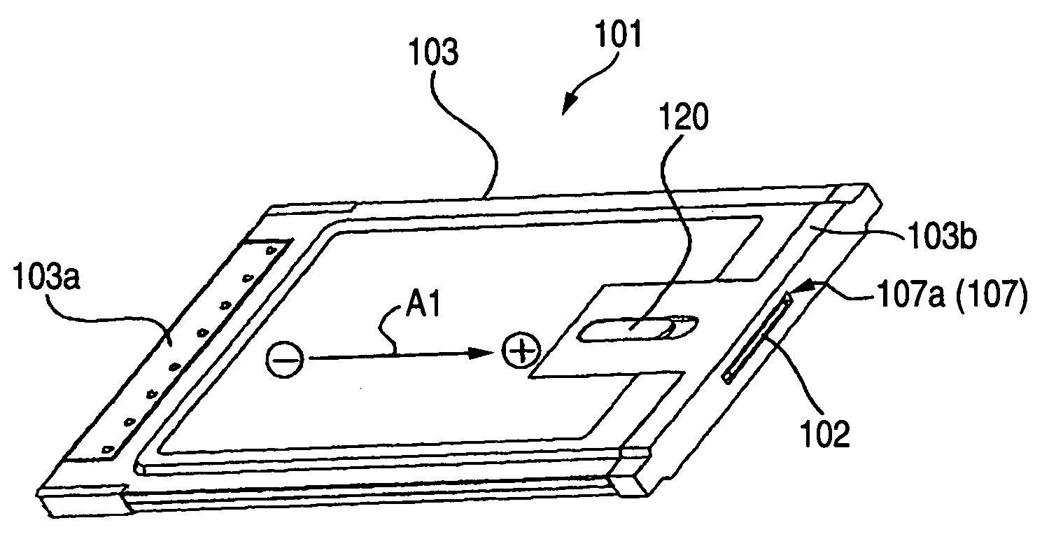
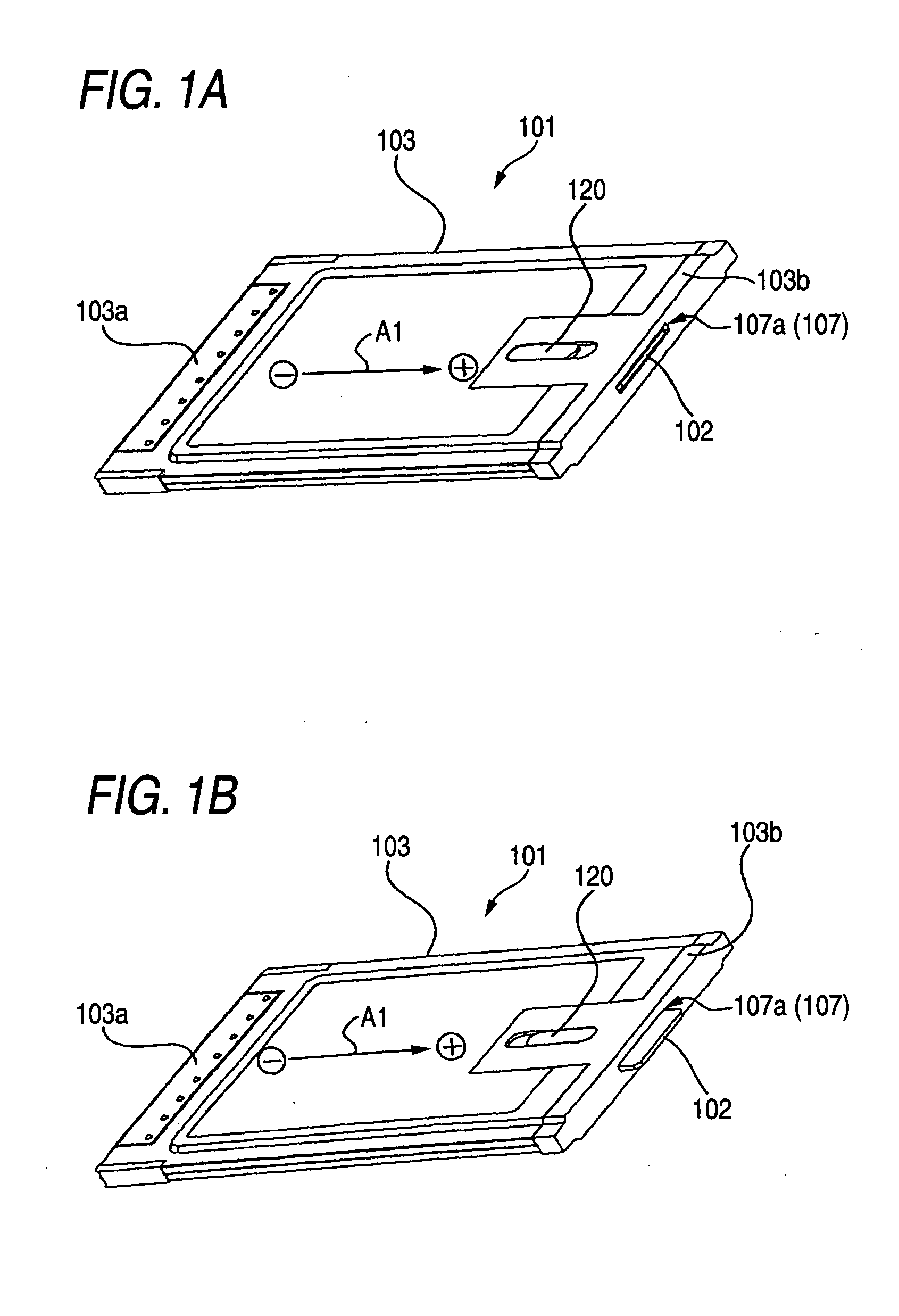
[0041] A first embodiment of the card for information equipment of the invention will be described with reference to FIGS. 1A, 1B, and 2.

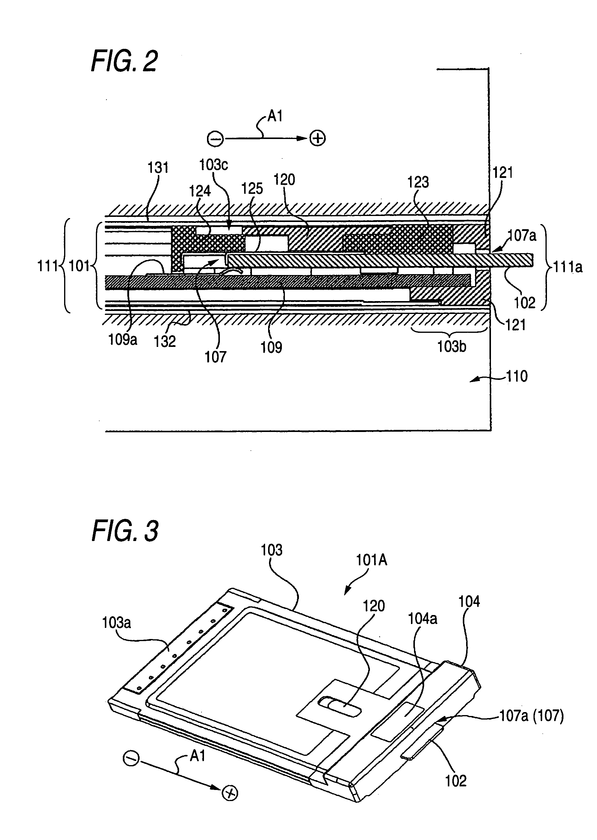
[0042]FIG. 1A is a perspective view schematically showing the configuration of a PC card of the first embodiment in a state where a SIM card is inserted, FIG. 1B is a perspective view showing the PC card in a state where the SIM card is ejected, and FIG. 2 is a section view showing the PC card of the first embodiment inserted to a PC, in a state where the SIM card is ejected.

[0043] As shown in FIG. 1A, 1B, or 2, the PC card 101 of the first embodiment is a PC card having a single plate-like shape, and, in a state where the SIM card 102 is connected and held and the PC card is inserted into a PC slot 111 of a PC 110, is used for expanding the function of the PC 110, or causing the PC to function as a radio communication terminal. The SIM card 102 incorporates a circuit board (not shown) on which identifying information is recorded, and has a recta...

Example

Second Embodiment

[0059] Next, a second embodiment of the card for information equipment of the invention will be described with reference to FIG. 3.

[0060]FIG. 3 is a perspective view schematically showing the configuration of a PC card of the second embodiment in a state where a SIM card is ejected.

[0061] As shown in FIG. 3, the PC card 101A of the second embodiment is a PC card with an extending portion consisting of the card body portion 103 and a card extending portion 104, and is different mainly from the first embodiment in that the chip slot 107 is disposed in the card extending portion 104. Hereinafter, this point will be described in detail, and, with the other configuration, the same reference numerals as those of the first embodiment are used and their description is omitted.

[0062] The card extending portion 104 is a thick case member which extends from the other end of the card body portion 103 in the longitudinal direction (the extracting direction of the SIM card 10...

Example

Third Embodiment

[0069] Next, a third embodiment of the card for information equipment of the invention will be described with reference to FIGS. 4A to 6B.

[0070]FIG. 4A is a plan view schematically showing the configuration of a PC card (in a state where a chip cover is opened) of the third embodiment, FIG. 4B is a rear view of the PC card, FIG. 5A is a plan view showing a state where the PC card of the third embodiment is inserted to a PC (in a state where the chip cover is substantially closed), FIG. 5B is a front view of the PC card and the PC, FIG. 6A is a plan view showing a state where the PC card of the third embodiment is inserted to the PC (in a state where the chip cover is opened), and FIG. 6B is a front view of the PC card and the PC.

[0071] As shown in FIG. 4A, 4B, 5A, or 5B, the PC card 201 of the third embodiment is, in a state where a SIM card 202 is connected and held and inserted into a PC slot 211 of a PC 210, used for expanding the function of the PC 210, or cau...


PUM


Abstract

A PC card has a card body portion in which a first card terminal portion is formed in one end and a second card terminal portion is formed in the other end. The card terminal portion has a chip slot. A SIM card inserted through an insertion port into the chip slot is electrically connected to a printed circuit board. The insertion port of the chip slot is opened in an outer side face of the second card terminal portion.

Description

CROSS-REFERENCE TO RELATED APPLICATIONS [0001] This application is based upon and claims the benefit of priority from the prior Japanese Patent Applications No. 2004-255645 filed on Sep. 2, 2004, No. 2004-255646 filed on Sep. 2, 2004, and No. 2004-255647 filed on Sep. 2, 2004, the entire contents of which are incorporated herein by reference. BACKGROUND OF THE INVENTION [0002] 1. Field of the Invention [0003] The present invention relates to a terminal for information equipment such as a PC card or a USB communication terminal which is to be inserted into information equipment such as a portable computer or a PDA (Personal Digital Assistant), and particularly a technique for connecting and holding a chip card on which identifying information is recorded, such as a SIM (Subscriber Identity Module) card, a UIM (User Identity Module) card, or a USIM (Universal Subscriber Identity Module) card, on a PC card or a terminal for information equipment. [0004] 2. Description of the Related Ar...

Claims


Application Information

Patent Timeline
IPC IPC(8): H01R13/62
CPCG06K19/077G06K19/07739H01R31/06H01R13/641H01R13/633Y10S439/945
Inventor UJII, JUNICHINAKASHIMA, MASATO
Owner DRNC HLDG INC
Why Eureka
Try Eureka