Area light source

a light source and area technology, applied in the direction of planar/plate-like light guides, lighting and heating apparatus, instruments, etc., can solve the problems of low luminance, low luminance, and ineffective introduction of primary light sources into light guides, so as to avoid the appearance of bright lines and appearance of dark parts, efficiently introduce light

Inactive Publication Date: 2006-03-16
MITSUBISHI RAYON CO LTD
View PDF7 Cites 39 Cited by
  • Summary
  • Abstract
  • Description
  • Claims
  • Application Information

AI Technical Summary

Benefits of technology

[0012] An object of the present invention is to provide a high-quality planar light source device capable of avoiding appearance of the bright line and appearance of the dark part at an area between the adjacent LED's, etc. observed within the effective lighting area of the planar light source device, and of efficiently introducing the light emitted from the primary light source such as LED, etc. into the light guide, even if the light guide is made thin and light.

Problems solved by technology

Additionally, in a case where the lighting portion of the LED is partly located higher than the upper edge of the light incident end face of the light guide, i.e. the edge thereof on the light emitting face side, there is another problem that luminance becomes lower because the light emitted from the LED is not efficiently introduced into the light guide.
However, these publications do neither suggest the above-mentioned problem that the dark shadows or dark parts are easily observed within the effective lighting area of the planar light source device at the intermediate portion between the adjacent LED's or the like when using the point light source such as LED as the primary light source, nor suggest measure against such a problem.
However, these publications also do neither suggest the above-mentioned problem that the dark shadows or dark parts are easily observed within the effective lighting area of the planar light source device at the intermediate portion between the adjacent LED's or the like when using the point light source such as LED as the primary light source, nor suggest measure against such a problem.
In addition, in this planar light source device, since the end region of the light incident end face of the light guide is covered with the edge of the reflector or edge of the lid, there is also the above problem that the light emitted from the primary light source is not efficiently introduced into the light guide and therefore the luminance becomes lower.
Accordingly, there is a problem that the light entered the gap between the light guide and the prism sheet is introduced into the prism sheet and emitted therefrom in an oblique direction, to thereby cause the bright line, in addition to the problem that the dark shadows or dark parts are easily observed within the effective lighting area of the planar light source device at the intermediate portion between the adjacent LED's or the like.

Method used


Image

  • Area light source
  • Area light source
  • Area light source

Examples


Embodiment Construction

[0041] Preferred embodiments of the present invention will be described hereunder with reference to the accompanying drawings.

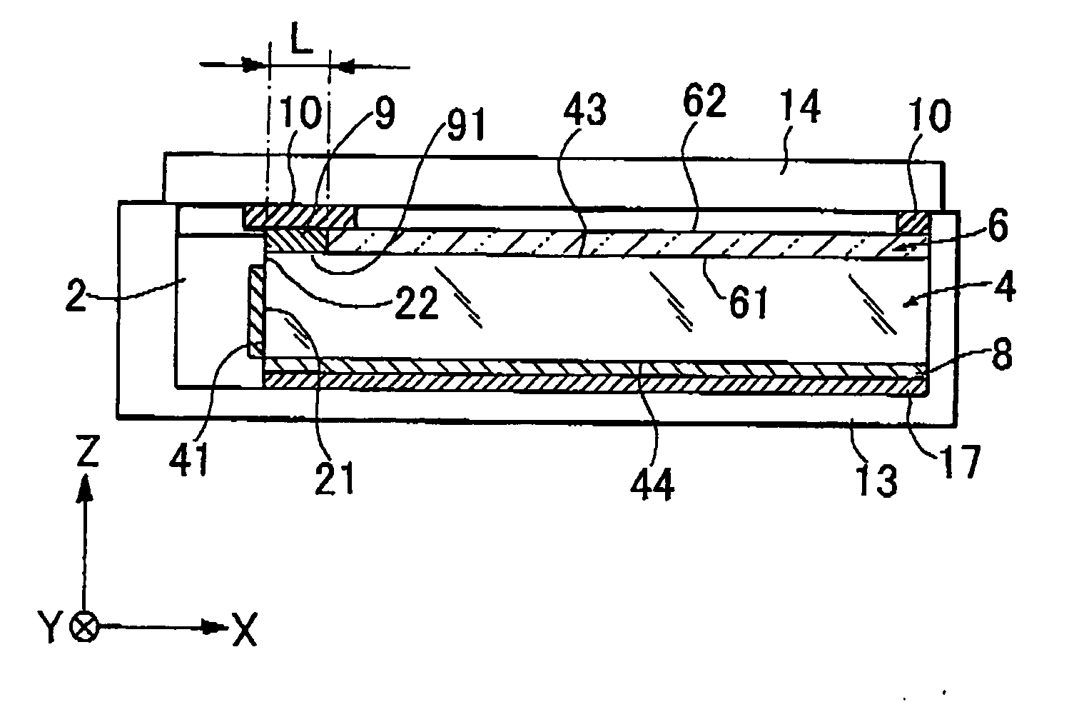
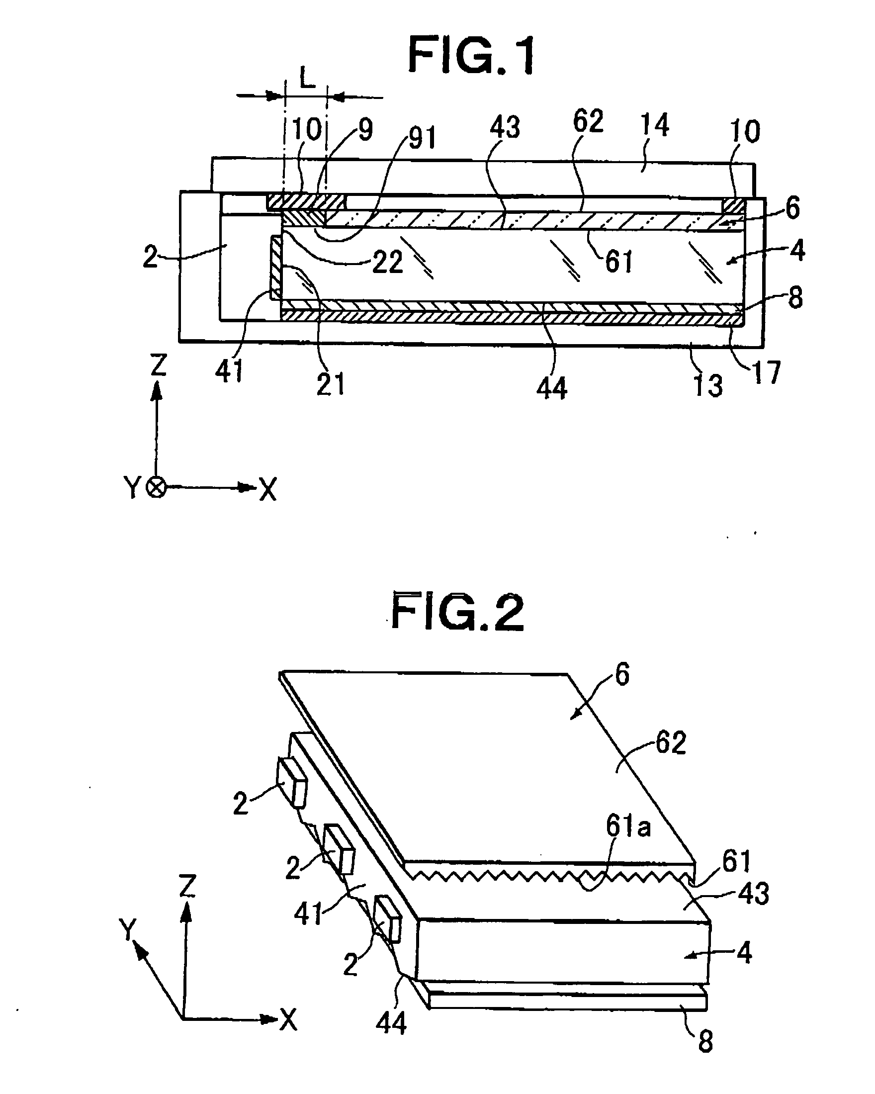
[0042]FIG. 1 is a schematic cross-sectional view showing an embodiment of a planar light source device of the present invention, and FIG. 2 is an exploded perspective view showing a portion of the constitution of the planar light source device of FIG. 1. As shown in FIGS. 1 and 2, the planar light source device of the embodiment comprises an LED 2 as a primary light source in a point state, a rectangular plate-like light guide 4 in an XY plane which makes a light emitted from the LED 2 incident on a light incident end face thereof, and guides the light therethrough to be emitted from a light emitting face thereof, and a light deflector 6 and a light reflector 8 both arranged adjacently to the light guide. The light guide 4 has two upper and lower principal surfaces, and four end faces for joining outer peripheries of the principal surfaces.

[0043] The LED 2 ...


PUM


Abstract

An area light source comprising an LED primary light source (2), a plate-like light guide (4) and a light deflector (6) is provided with a direct light incoming prevention means closed of a light-blocking member (9). The light guide (4) has a light incoming end face (41) and a light outgoing face (43) and guides a light emitted from the LED primary light source (2). The light deflector (6) is arranged adjacently to the light outgoing face (43) and has a light entering face (61) and a light exiting face (62). The direct light incoming prevention means prevents a light, which is emitted from the LED primary light source (2), from entering into the light deflector (6) without passing through the light guide (4). The light-blocking deflector (9) is disposed on a first region of the light outgoing face (43) which is located near the edge of the light incoming end face side of the light outgoing face (4). The surface of the light-blocking member (9) facing the light outgoing face (43) is a diffusing reflective surface. The light deflector (6) is disposed on a second region of the light outgoing face (43) where the light-blocking member (9) is not arranged.

Description

TECHNICAL FIELD [0001] The present invention relates to a planar light source device of an edge light system, and more particularly to a planar light source device or area light source designed to realize miniaturization and a reduction in power consumption. The planar light source device of the present invention is suitably applied to a backlight, which uses a point light source such as a light emitting diode (LED), of a relatively compact liquid crystal display device used as a display panel of a portable electronic device such as a cellular phone, or an indicator of various devices. BACKGROUND ART [0002] Recently, the liquid crystal display device has been in wide use as a monitor for a portable notebook personal computer or the like, or a display section for a liquid crystal television, a video integrated liquid crystal television or the like, and in various other fields. The liquid crystal display device basically comprises a backlight section and a liquid crystal display eleme...

Claims


Application Information

Patent Timeline
Patent Type & Authority Applications(United States)
IPC IPC(8): F21V7/04F21V8/00G02B6/00G02B6/42
CPCG02B6/0013G02B6/4298G02B6/0053G02B6/0038G02F1/1335G02B6/0001
Inventor YAMASHITA, TOMOYOSHIHAYASHI, YASUKO
Owner MITSUBISHI RAYON CO LTD
Why Eureka
Try Eureka