
Voice code conversion apparatus
a voice code and code technology, applied in the field of voice code conversion apparatus, can solve the problems of delay in processing, marked decline in the and inferior sound quality of reproduced voi
- Summary
- Abstract
- Description
- Claims
- Application Information
AI Technical Summary
Benefits of technology
Problems solved by technology
Method used
Image

Examples
first embodiment
(B) First Embodiment
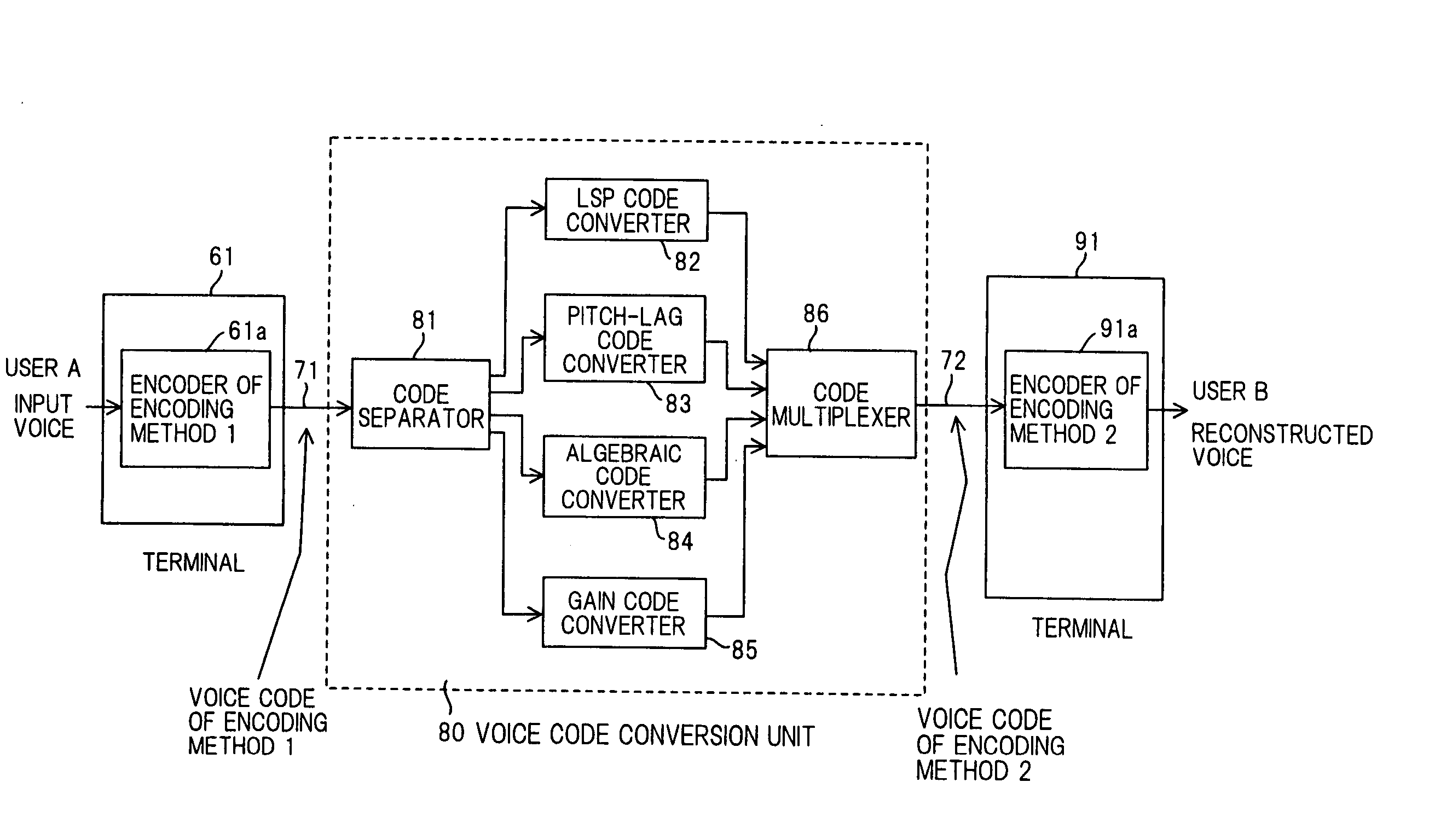
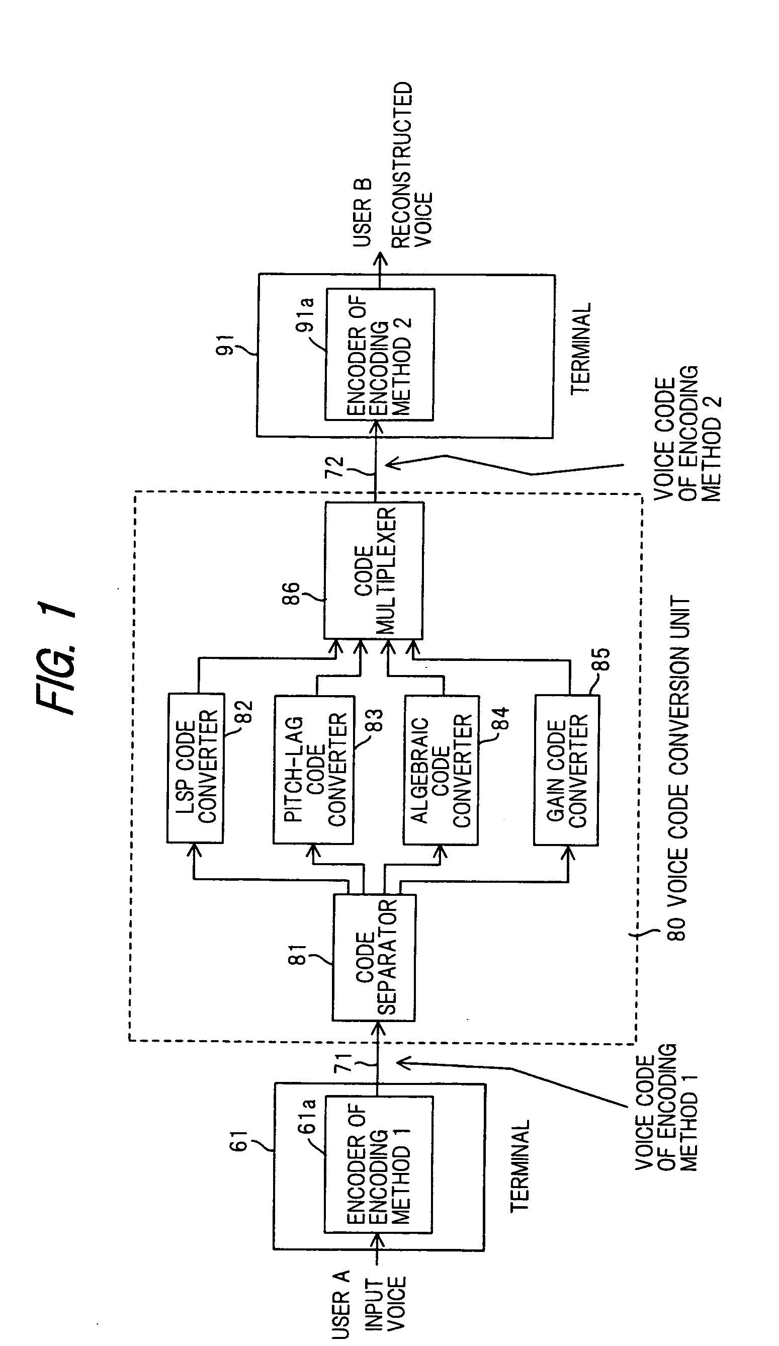
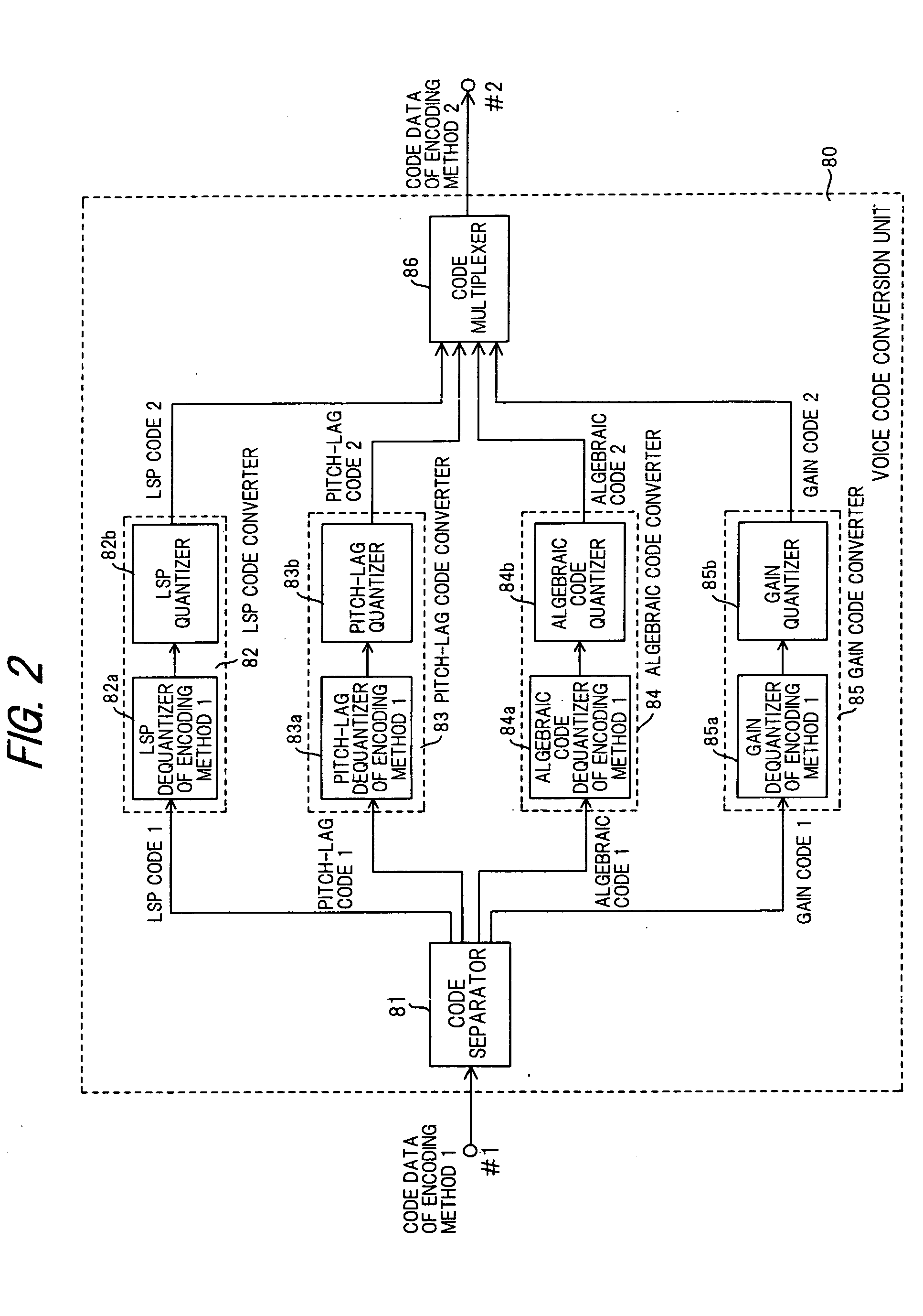
[0092]FIG. 3 is a block diagram illustrating a voice code conversion unit according to a first embodiment of the present invention. Components identical with those shown in FIG. 2 are designated by like reference characters. This arrangement differs from that FIG. 2 in that a buffer 87 is provided and in that the gain quantizer of the gain code converter 85 is constituted by an adaptive codebook gain quantizer 85b1 and a noise codebook gain quantizer 85b2. Further, in the first embodiment shown in FIG. 3, it is assumed that the G.729A encoding method is used as encoding method 1 and the AMR method as the encoding method 2. Though there are eight encoding modes in AMR encoding, in this embodiment use is made of an encoding mode having a transmission rate of 7.95 kbps.
[0093] As shown in FIG. 3, an nth frame of channel data bst1(n) is input to terminal #1 from a G.729A encoder (not shown) via the transmission path. Here the bit rate of G.729A encoding is 8 kbps and...
second embodiment
(C) Second Embodiment
[0141]FIG. 11 is a diagram useful in describing an overview of a second embodiment of the present invention. The second embodiment improves upon the LSP quantizer 82b in the LSP code converter 82 of the first embodiment; the overall arrangement of the voice code conversion unit is the same as that of the first embodiment (FIG. 3).
[0142]FIG. 11 illustrates a case where LSP code of nth and (n+1)th frames of the G.729A method is converted to LSP code of the mth frame of the AMR method. In FIG. 11, LSP0(i) (i=1, . . . , 10) represent 10-dimensional LSP dequantized values in a first subframe (1st subframe) of an nth frame according to the G.729A method, and LSP1(i) (i=1, . . . , 10) represent 10-dimensional LSP dequantized values in a first subframe (1st subframe) of an (n+1)th frame according to the G.729A method. Further, old_LSP(i) (i=1, . . . , 10) represent 10-dimensional LSP dequantized values in a 1st subframe of a past frame [(n−1)th frame].
[0143] In a case...
third embodiment
(D) Third Embodiment
[0172] The third embodiment improves upon the LSP quantizer 82b in the LSP code converter 82 of the second embodiment. The overall arrangement is the same as that of the first embodiment shown in FIG. 3.
[0173] The third embodiment is characterized by making a preliminary selection (selection of a plurality of candidates) for each of the small vectors of the low-, midrange- and high-frequency regions, and finally deciding a combination {I1, I2, I3) of LSP code vectors for which the errors in all bands will be minimal. The reason for this approach is that there are instances where the 10-dimensional LSP synthesized code vector synthesized from code vectors for which the error is minimal in each band is not the optimum vector. In particular, since an LPC synthesis filter is composed of LPC coefficients obtained by conversion from 10-dimensional LSP parameters in the AMR or G.729A method, the conversion error in the LSP parameter region exerts great influence upon r...
PUM
 Abstract
Description
Claims
Application Information