Pitch drive system for a wind turbine

a technology of pitch drive and wind turbine, which is applied in the direction of rotors, marine propulsion, vessel construction, etc., can solve the problems of yield loss, approach failure, and complex drive train structure, and achieve the effect of saving space and not reducing yield

Inactive Publication Date: 2006-04-20
GENERAL ELECTRIC CO
View PDF5 Cites 20 Cited by
  • Summary
  • Abstract
  • Description
  • Claims
  • Application Information

AI Technical Summary

Benefits of technology

[0013] The separation of the drive trains of the regulation drive and the emergency drive lowers the complexity of the individual drive train assembly. Furthermore, the pitch drive system can be designed in a modular manner which does not only facilitate the assembly of the system but does also increase the operational safety and reliability. Particularly, the risk that the emergency drive cannot operate due to a gear box failure of the regulation drive is eliminated. This reliability aspect is especially important for off-shore applications where maintenance is costly, complicated and scheduled at large intervals.
[0015] Thus is a further redundancy of the emergency drive provided so that the operational safety and reliability of the pitch drive system are further improved. Particularly, the separation of the emergency drive into two or more separate drive trains reduces the risk of a failure of the emergency drive because of enhanced redundancy. A further advantage of this embodiment is that a modular structure of the emergency drive can be established. For example, emergency drive modules providing a predetermined torque can be manufactured independently from the design of the wind turbine pitch drive. When dimensioning the emergency drive, a sufficient number of these modules is assembled to provide the required total torque to feather the rotor blade. Furthermore, more emergency drive modules than necessary can be assembled to provide redundancy so that sufficient torque is applied even in a case where one or more emergency drive modules fail.
[0017] The regulation drive according to this aspect prevents a system shutdown when one of the motors fails since the other motor can still operate the regulation drive. Thus, the wind turbine can stay in operation and the yield is not reduced. Furthermore, the redundancy requirements for the regulation drive are not as high as for the emergency drive. Therefore, the small risk that a gear box failure occurs is acceptable for the regulation drive. The more important aspect with respect to the regulation drive is that the motors are coupled to the same gear box so that space is saved.

Problems solved by technology

Thus, the structure of the drive train becomes very complicated.
However, such an approach may fail when the electronics of the wind turbine is damaged, e.g., by lightning.
A further problem associated with the above prior art pitch drive systems is that failure in the electrical drive system leads to a shutdown of the wind turbine so that a yield loss occurs.
Accordingly, the pitch drive system of DE 101 16 011 is still fault-prone in cases where the electronics of the wind turbine is damaged, e.g., by lightning.

Method used


Image

  • Pitch drive system for a wind turbine
  • Pitch drive system for a wind turbine
  • Pitch drive system for a wind turbine

Examples


Embodiment Construction

[0030] Reference will now be made in detail to the various embodiments of the present invention, one or more examples of which are illustrated in the figures. Each example is provided by way of explanation of the invention, and is not meant as a limitation of the invention. For example, features illustrated or described as part of one embodiment can be used on or in conjunction with other embodiments to yield yet a further embodiment. It is intended that the present invention includes such modifications and variations.

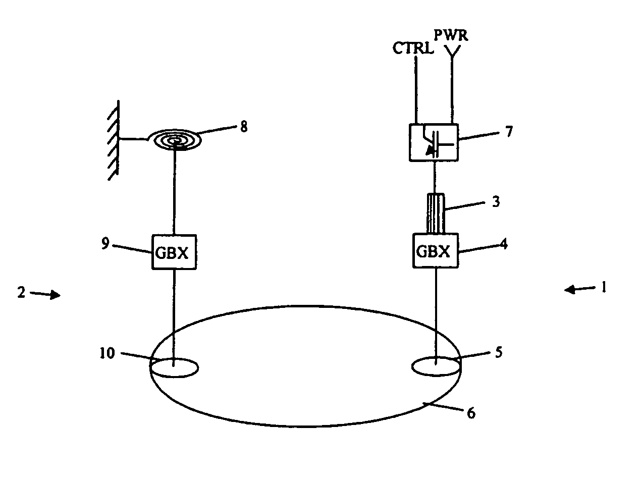
[0031]FIG. 1 shows an embodiment of the present invention according to a first embodiment of the present invention. Therein, the pitch drive system comprises a regulation drive 1 and an emergency drive 2. The regulation drive 1 and the emergency drive 2 comprise separate drive trains. Thus, the complexity of the individual drive train assemblies 1, 2 is lowered compared to drive trains where regulation drive and emergency drive share a drive train.

[0032] The regulati...


PUM


Abstract

A pitch drive system for a wind turbine is provided which comprises a regulation drive for regulating the pitch of a rotor blade of the wind turbine during normal operation, the regulation drive comprising at least one drive train, and an emergency drive for pitching the rotor blade in case of emergency, the emergency drive comprising at least one drive train, wherein the at least one drive train of the emergency drive is separate from the at least one drive train of the regulation drive.

Description

[0001] The present application claims priority to corresponding EP Application No. 04024520.1, filed on Oct. 14, 2004, the entire contents of which are hereby incorporated by reference. FIELD OF THE INVENTION [0002] The present invention relates to a pitch drive system for a wind turbine, particularly to a pitch drive system which comprises a regulation drive for regulating the pitch of a rotor blade of the wind turbine during normal operation, and an emergency drive for pitching the rotor blade in case of emergency. The present invention further relates to wind turbines with pitch drive systems comprising both a regulation drive and an emergency drive. BACKGROUND OF THE INVENTION [0003] Typically, modern wind turbines have rotor blades with adjustable pitch angle. The rotor blades can be rotated about their longitudinal axis by use of a pitch drive disposed in the rotor hub. Typically, the pitch drive is actuated electrically or hydraulically. By adjusting the pitch angles of the r...

Claims


Application Information

Patent Timeline
Patent Type & Authority Applications(United States)
IPC IPC(8): B64C27/54
CPCF03D7/0224F05B2270/107F05B2270/602F05B2270/604F05B2270/606Y02E10/723Y02E10/72
Inventor ROGALL, PETERACHENBACH, PATRICK
Owner GENERAL ELECTRIC CO
Why Eureka
Try Eureka