Method for operating a camshaft adjusting device

a camshaft and camshaft technology, applied in mechanical equipment, machines/engines, electric control, etc., can solve the problems of vehicle behavior with respect to engine power, response behavior change, exhaust emission behavior of the vehicle,

Inactive Publication Date: 2006-05-11
ROBERT BOSCH GMBH
View PDF2 Cites 2 Cited by
  • Summary
  • Abstract
  • Description
  • Claims
  • Application Information

AI Technical Summary

Benefits of technology

[0004] It is an object of the present invention to make possible a more discriminating reaction in response to the occurrence of system deviations between the setpoint value for the setting of the camshaft and the input actual value.

Problems solved by technology

Independent of whether a camshaft adjusting device has its own drive or one that is coupled to other devices, the problem arises that, when inaccurate regulation occurs, first, the exhaust emission behavior of the vehicle changes, and, secondly, also the vehicle behavior with respect to engine power and the response behavior change.

Method used


Image

  • Method for operating a camshaft adjusting device
  • Method for operating a camshaft adjusting device

Examples


Embodiment Construction

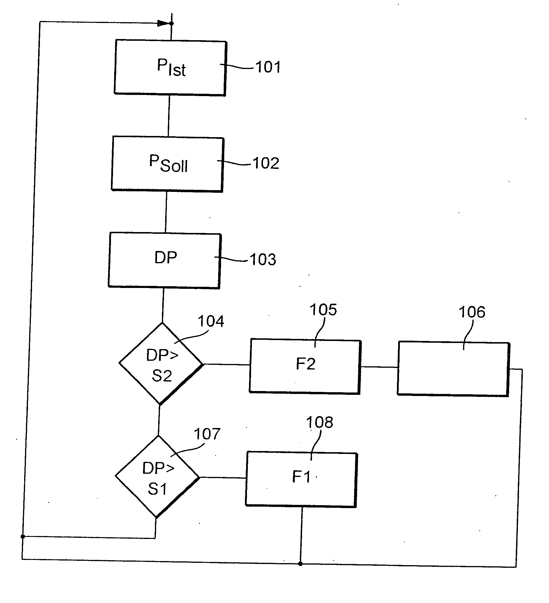
[0015]FIG. 1 shows the flowchart of a method according to the present invention. In the method shown in FIG. 1, in this context, two stages of fault indication are differentiated from each other.

[0016] According to step 101 of the method, first of all the value for the actual setting of the camshaft Pactual with respect to the crankshaft is recorded and supplied.

[0017] Subsequently, according to step 102, the setpoint value of the position of camshaft actuator Psetpoint is supplied. In step 103 of the method, the system deviation DP is ascertained from it. According to step 104 of the method, it is then checked whether system deviation DP is greater than a second threshold value F2. This second threshold value is the threshold for crossing over to a stage of a fault of higher weightiness. Thus, in the method it is first checked whether a fault of the greatest weightiness is present, which as a rule is distinguished by the greatest system deviation DP. If so, according to step 105 ...


PUM


Abstract

In a method for operating a camshaft adjusting device, using an actuating drive, the actual setting of a camshaft with respect to the rotation of the crankshaft is followed corresponding to a setpoint setting ascertained in a control unit. In response to the occurrence of a lasting system deviation between the actual setting and the setpoint setting, an error signal is generated. The error signal is designed in multiple stages as a function of the system deviation, different weightings being imputed to the individual stages of the fault indication. By this measure, the fault indications of different weightings may be processed. Faults that are not serious, but nevertheless require attention, may be treated separately from serious faults.

Description

BACKGROUND INFORMATION [0001] Camshaft adjusting devices are generally known in which, using an actuating drive, the actual setting of a camshaft with respect to the rotation of the crankshaft is followed corresponding to a setpoint setting ascertained in a control unit. [0002] In this context, in principle, two types of camshaft adjusting devices are known. In one type, the generating of camshaft adjustment takes place independently of other assemblies. For this, for example, electrical camshaft actuators may be used. The other type of camshaft adjusting devices are those in which the energy required for generating the camshaft adjustment is fed directly by an ancillary component of the internal combustion engine, such as, for instance, the oil-pressure pump of the engine oil circulation. [0003] Independent of whether a camshaft adjusting device has its own drive or one that is coupled to other devices, the problem arises that, when inaccurate regulation occurs, first, the exhaust ...

Claims


Application Information

Patent Timeline
Patent Type & Authority Applications(United States)
IPC IPC(8): F01L1/34F02D41/22
CPCF01L1/34F02D41/221F02D2041/001Y02T10/40
Inventor HAFFELDER, JOERGKRANNICH, OLIVERMEZGER, WERNER
Owner ROBERT BOSCH GMBH
Why Eureka
Try Eureka