Flush syringe having compressible plunger

a plunger and syringe technology, applied in the field of syringe assemblies, to achieve the effect of reducing or eliminating the compression of the distal end, reducing or eliminating the reflux of blood, and reducing or eliminating the compression of the stopper

Inactive Publication Date: 2006-05-11
ALHEIDT THOMAS A +2
View PDF24 Cites 57 Cited by
  • Summary
  • Abstract
  • Description
  • Claims
  • Application Information

AI Technical Summary

Benefits of technology

[0008] The present invention is directed to a syringe for use in flush applications. The syringe reduces or eliminates compression of distal end of the stopper at the completion of the flush procedure thereby reducing or eliminating reflux of blood into the catheter. Compression of the stop

Problems solved by technology

This is undesirable, since it can cause blood to ent

Method used


Image

  • Flush syringe having compressible plunger
  • Flush syringe having compressible plunger
  • Flush syringe having compressible plunger

Examples


Embodiment Construction

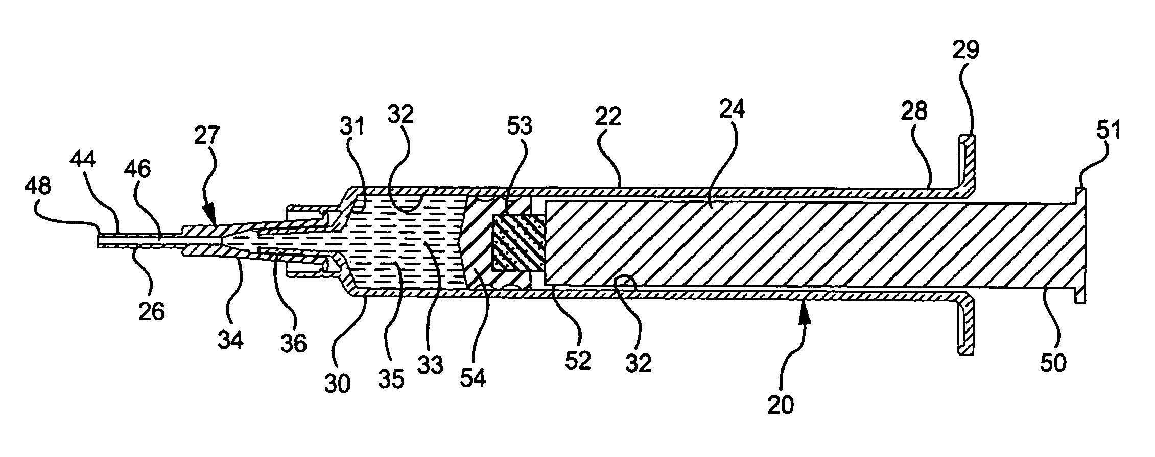
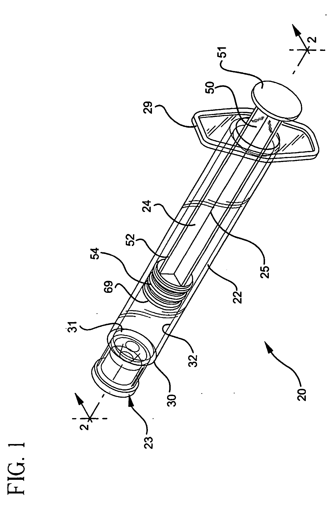
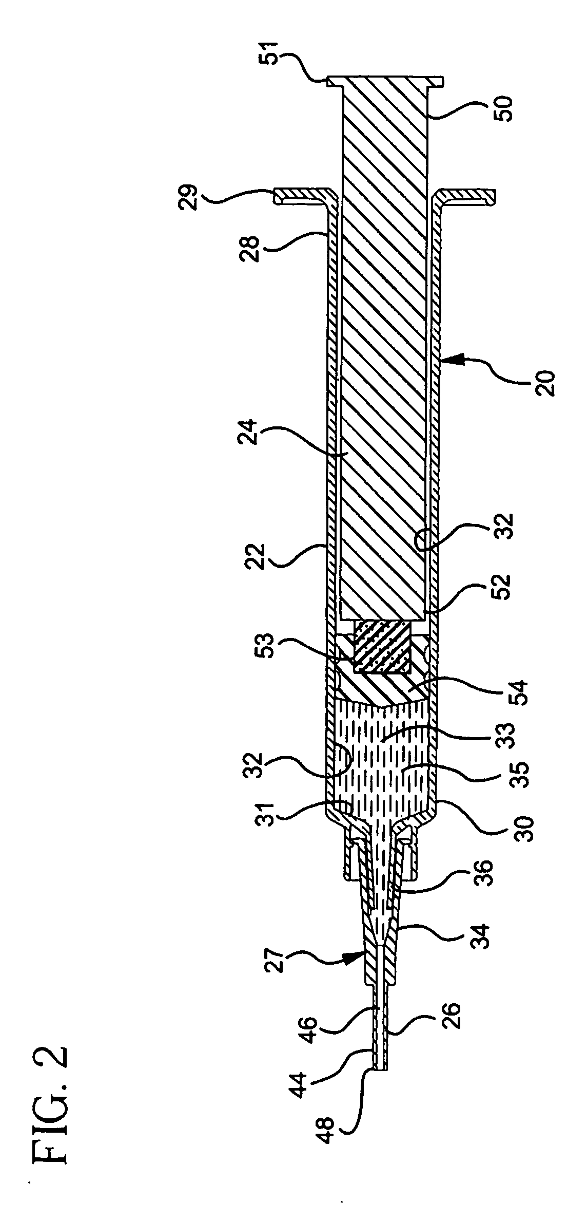
[0026]FIG. 1 shows a syringe 20 according to the present invention generally comprising a barrel 22 and a plunger 24. The barrel 22 has a generally elongate body including an open proximal end 28 having finger grips 29, a distal end 30 having a distal wall 31 and an inside surface 32 defining a chamber 33 for retaining fluid. The distal end 30 further includes a tip 36 having a passageway 38 in fluid communication with the chamber. The distal end of barrel 22 preferably, but not necessarily includes a locking luer type collar 40 concentrically surrounding tip 36. The inside surface of the collar includes at least one thread 43. A cannula 26 includes a proximal end 42, a distal end 44 and a lumen 46 therethrough. The distal end may include a sharp tip or a blunt tip 48 as shown. The cannula may be connected directly to the tip of the syringe barrel to establish fluid communication between the lumen and the chamber. Also, the cannula may be part of a needle assembly 27 including a hub...


PUM


Abstract

An I.V. flush syringe assembly includes a barrel having an inside surface defining a chamber for retaining fluid, an open proximal end and a distal end with a passageway therethrough in fluid communication with the chamber. An elongate plunger having a proximal end, a distal end and a stopper is slidably positioned in fluid-tight engagement with the inside surface of the barrel for drawing fluid into and out of the chamber by movement of the stopper relative to the barrel. The plunger includes anti-reflux structure for minimizing stopper deflection when fluid has been delivered from the chamber and the stopper is being forced against the distal end of the chamber.

Description

[0001] This application claims priority from U.S. Provisional Application No. 60 / 417,954, filed Oct. 11, 2002.BACKGROUND OF THE INVENTION [0002] The present invention relates to syringe assemblies and particularly to syringe assemblies for use in I.V. flush procedures. [0003] An I.V. catheter is a commonly used therapeutic device. Many patients, in accordance with their therapy, have an I.V. catheter connected to a vein ready for use in various procedures or in fluid communication with an I.V. system for infusing liquids and medication. Many I.V. sets have I.V. ports which are in fluid communication with a catheter and allow access for the purpose of injecting medication into the patient, and for use in flushing techniques to maintain catheter integrity. Healthcare facilities have flushing protocols which depend on the amount of time the catheter will remain in the patient and the type of catheter being used. For example, a peripherally inserted central catheter (PICC) is a long fle...

Claims


Application Information

Patent Timeline
IPC IPC(8): A61M5/178A61M5/315A61M25/00
CPCA61M5/31511A61M5/31515A61M2005/31523A61M2202/0478A61M5/31513A61M5/3293A61M5/31505
Inventor ALHEIDT, THOMAS A.HOTTOVY, TRACY RAYTIMKO, JAMES JOHN
Owner ALHEIDT THOMAS A
Why Eureka
Try Eureka