Ultramicrotome device

a microtome and ultra-microtome technology, applied in the direction of withdrawing sample devices, preparing samples for investigation, sawing apparatus, etc., can solve the problems of extreme care to shield and adversely affect cutting, and achieve the effect of reducing distortion

Inactive Publication Date: 2006-11-30
ANTON MEYER & CO AG
View PDF13 Cites 5 Cited by
  • Summary
  • Abstract
  • Description
  • Claims
  • Application Information

AI Technical Summary

Benefits of technology

[0015] In order to preserve the original ultrastructure and form of matter, it would be desirable to eliminate the distortion (compression) in the sections 4.

Problems solved by technology

In ultramicrotomy the sections are so thin that extreme care must be taken to shield the ultramicrotome from all possible external and internal vibrations because they would adversely affect the cutting result.
However, in ultramicrotomy a different problem arises which does not occur in microtomy: the problem of section compression.

Method used


Image

  • Ultramicrotome device
  • Ultramicrotome device
  • Ultramicrotome device

Examples


first embodiment

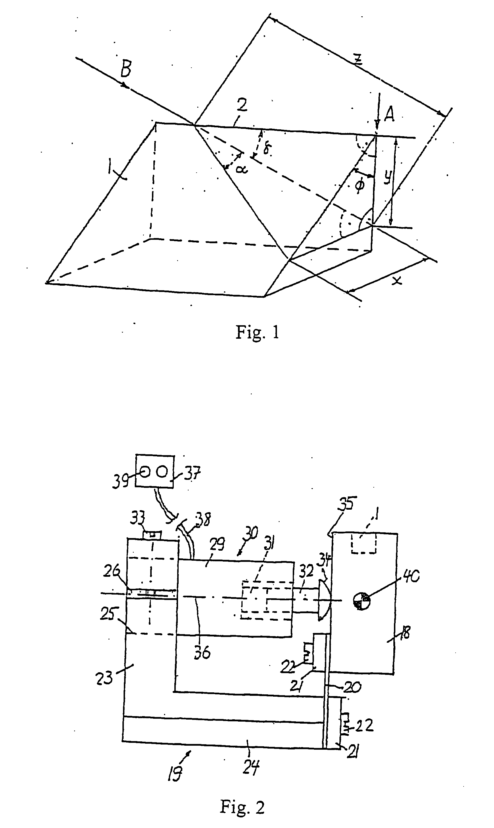
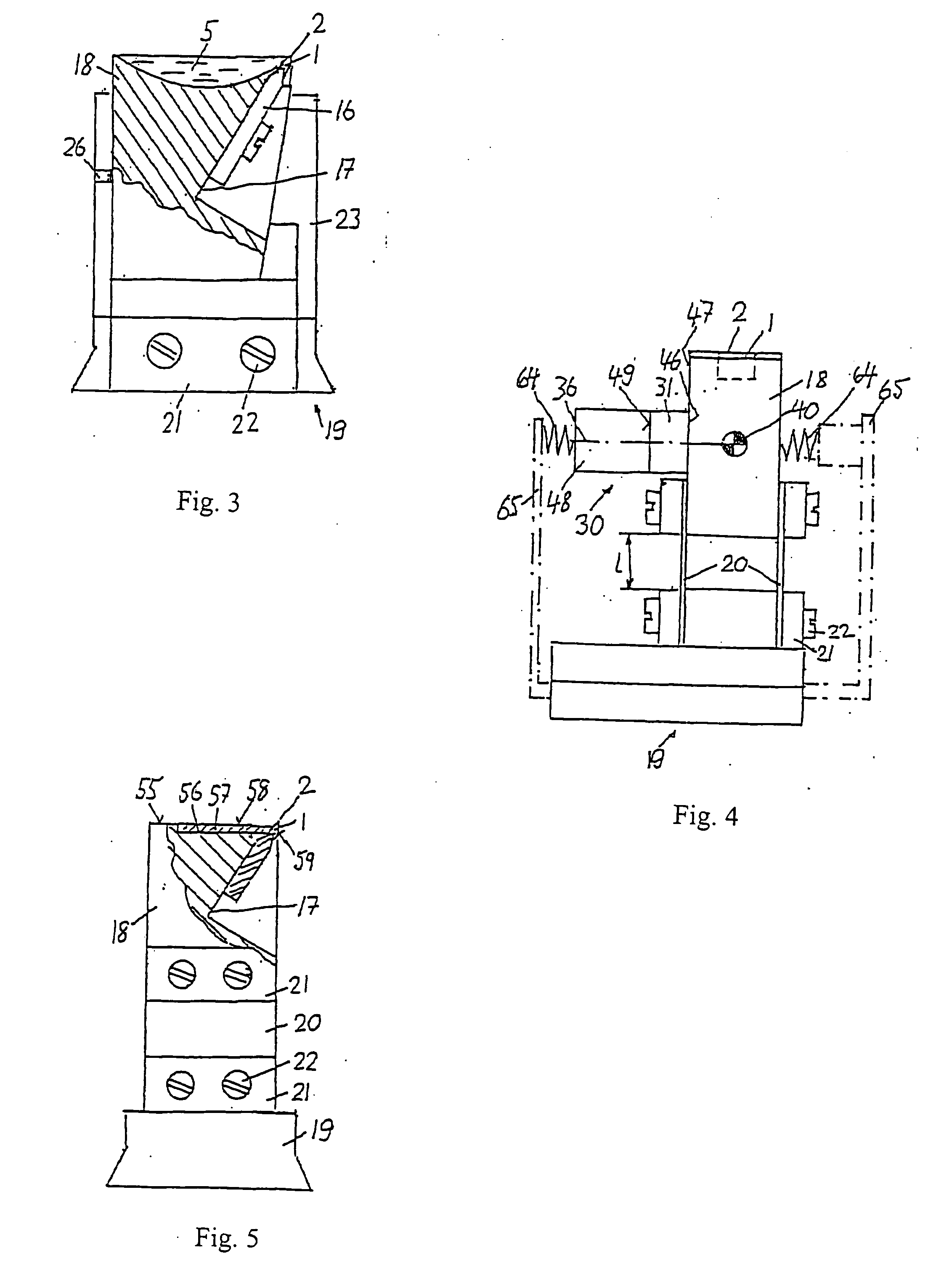
[0030] the invention is shown in FIGS. 2 and 3. The blade 1 is sintered in a bronze holder 16 or vacuum brazed in a tungsten carbide holder. The holder 16 is mounted on an inclined face of a recess 17 in a block 18. The block 18 is mounted to a holder 19 by means of a leaf spring 20. The plane of the leaf spring 20 is substantially vertical and perpendicular to the cutting edge 2. The spring 20 is mounted to the block 18 and the holder 19 by flat plates 21 and screws 22. Alternatively, the spring 20 may be designed as an integral part of the block 18 and the holder 19.

[0031] An arm 23 extends upward from the base 24 of the holder 19. The arm 23 has a cylindrical horizontal boring 25 and a slot 26 on one side. The cylindrical housing 29 of a vibrator 30 with a piezoelectric transducer 31 and an actuating rod 32 is held in the boring 25 by means of a screw 33. The spherical face end 34 of the rod 32 is slightly pressed against a plane face 35 of the block 18. The axis 36 of the vibrat...

third embodiment

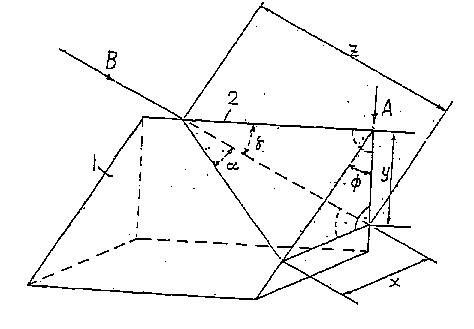
[0038]FIGS. 6 and 7 show a Similar parts are again designated with the same reference numerals. In this embodiment, the holder 19, the block 18 and the leaf spring 20 are manufactured from a single piece of metal. The spring 20 is a web connecting the holder 19 and the block 18. The holder 19 is mounted on a base 72. In operation, the block 18 oscillates with an amplitude ao and with a frequency in radians ω=2π·ν, wherein ν is the frequency in Hz, in a horizontal first direction x parallel to the cutting edge 2. The oscillating movement is ao sin ωt and the oscillating speed vh is ao ω cos ωt.

[0039] A first slide 73 is slidably guided on first guide rails 74 of the base 72 which extend in a horizontal second direction y perpendicular to the first direction x. The movement of the slide 73 is controlled by a first actuator 75 for stepwise advance of the probe 3 towards the cutting edge 2 between successive cuts. Second guide rails 76 are mounted on the slide 73 and extend in the vert...


PUM

PropertyMeasurementUnit
thicknessaaaaaaaaaa
frequencyaaaaaaaaaa
thicknessaaaaaaaaaa

Abstract

In a process for cutting sections from a probe for microscopic analysis, an ultramicrotome device is used having a blade with a cutting edge, the cutting edge extending at least approximately in a first direction. The process includes the steps of: vibrating the blade in the first direction; and moving the blade relative to the probe to be cut in a second direction, the second direction being perpendicular to the first direction. This eliminates, or at least strongly reduces, compression of the cut sections.

Description

CROSS REFERENCE TO RELATED APPLICATIONS [0001] This application is a continuation of U.S. patent application Ser. No. 10 / 646,354, filed Aug. 22, 2003, which is a continuation-in-part of U.S. patent application Ser. No. 09 / 718,636, filed Nov. 22, 2000, which is a continuation-in-part of U.S. patent application Ser. No. 09 / 207,284, filed Dec. 8, 1998, which claims priority to European Patent No. EP 97 811 004.7, filed Dec. 19, 1997, all of which are incorporated herein by reference in their entirety.BACKGROUND OF THE INVENTION [0002] 1. Field of the Invention [0003] The present invention relates to a process for cutting sections from a probe for microscopic analysis by using an ultramicrotome device. [0004] 2. Description of Related Art [0005] Microtomes and ultramicrotomes are used to cut thin respective ultra-thin sections from a sample for microscopic analyses. The sample is mounted on a cross-slide which can be advanced horizontally in steps according to the desired thickness of t...

Claims


Application Information

Patent Timeline
Patent Type & Authority Applications(United States)
IPC IPC(8): B26D1/00B26D7/08G01N1/06G01N1/36
CPCB26D7/086G01N2001/063G01N1/36G01N1/06Y10T83/04Y10T83/0538Y10T83/6508Y10T83/97
Inventor STUDER, DANIEL
Owner ANTON MEYER & CO AG
Why Eureka
Try Eureka