Impact deflection system

a technology of impact deflection and system, which is applied in the direction of antenna details, antenna adaptation in movable bodies, antennas, etc., can solve the problems of large antenna parts breaking, prone to being struck, and damage to various parts of the aircra

Active Publication Date: 2006-06-15
THE BOEING CO
View PDF5 Cites 11 Cited by
  • Summary
  • Abstract
  • Description
  • Claims
  • Application Information

AI Technical Summary

Benefits of technology

[0006] An object deflection system according to a preferred embodiment of the invention includes at least one sensor for detecting an impending impact of a first object with a second object. The sensor communicates with a deflector deployment device to substantially instantaneously activate the defl...

Problems solved by technology

Typically, the height of the antennas makes it prone to being struck by airborne objects, such as a bird, for which the radome provides little protection.
Such a failure could cause large portions of the antenna to break away while in flight, which can damage various parts of the aircraft, such as the vertical stabilizer, the horizontal stabilizer or the rear engines.
An antenna structure capable of withstanding such an impact can be costly, heavy, and impractical without significant compromise to the satellite tracking performance of t...

Method used


Image

  • Impact deflection system
  • Impact deflection system
  • Impact deflection system

Examples


Embodiment Construction

[0020] The following description of the preferred embodiments is merely exemplary in nature and is in no way intended to limit the invention, its application or uses. Additionally, the advantages provided by the preferred embodiments, as described below, are exemplary in nature and not all preferred embodiments provide the same advantages or the same degree of advantages.

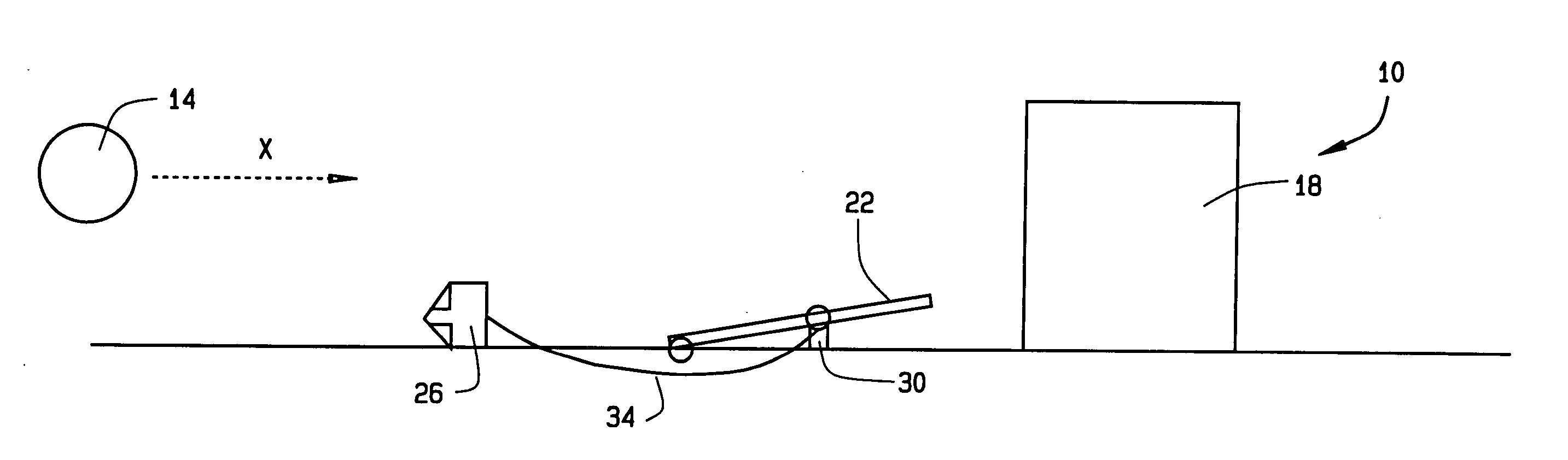
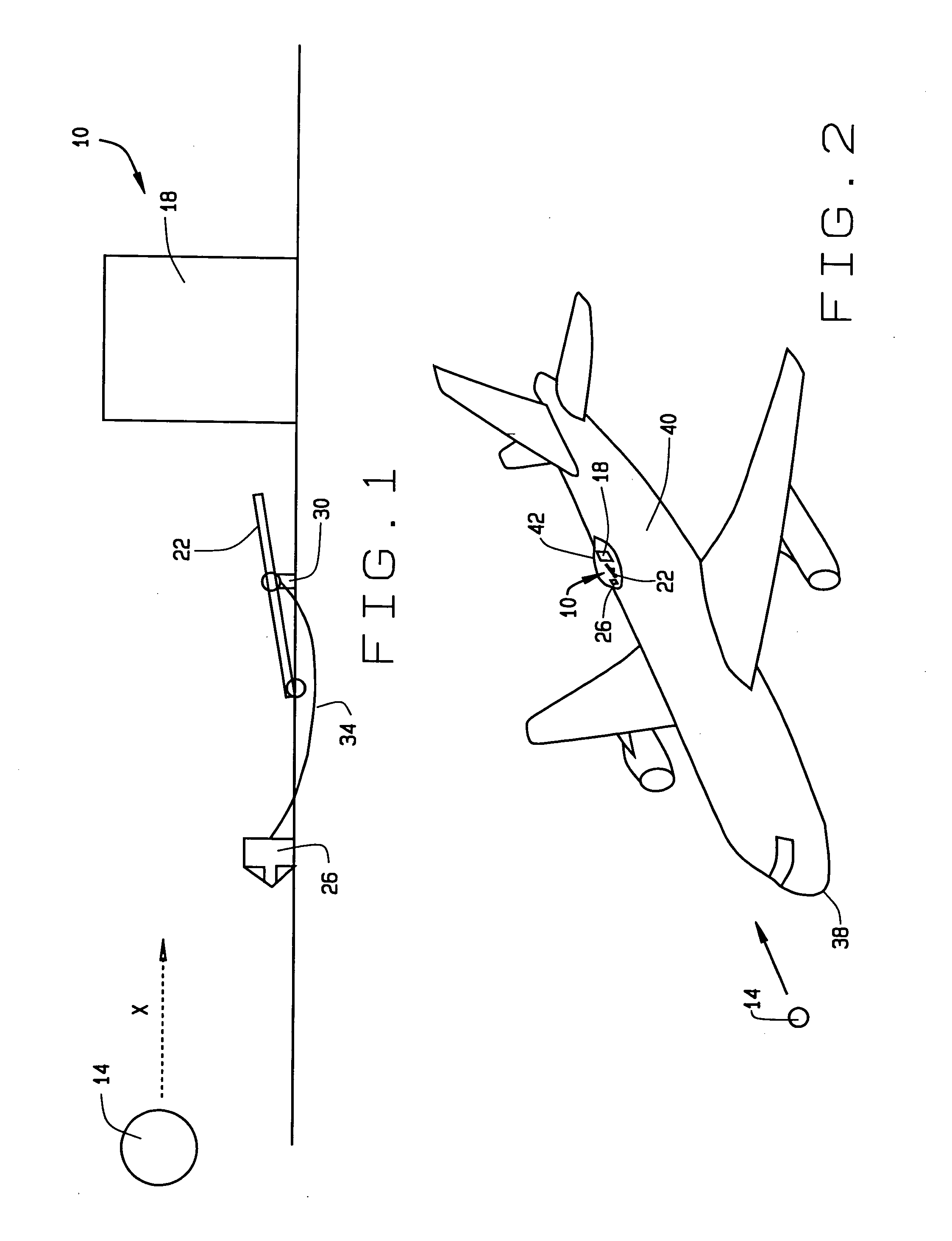
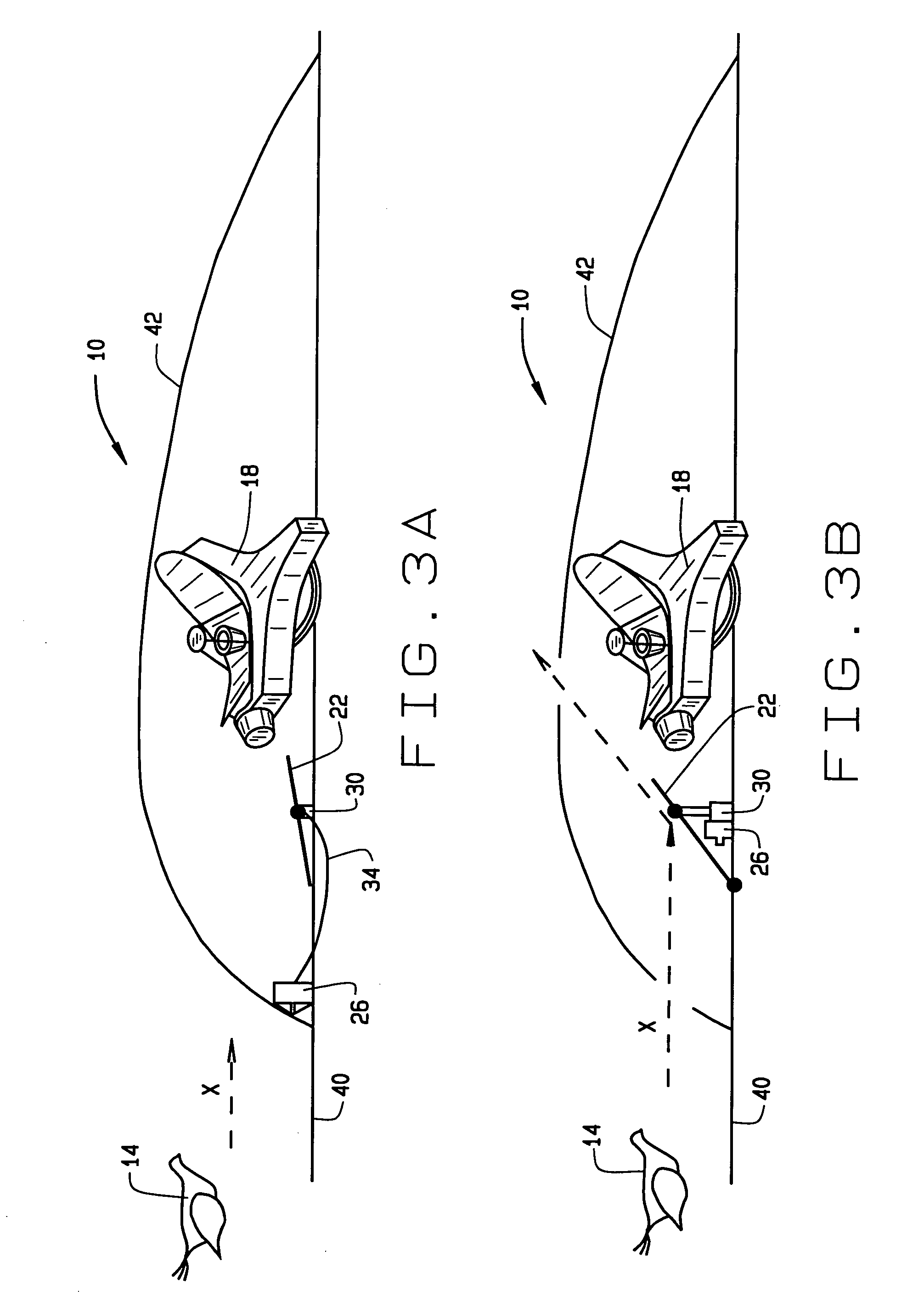
[0021]FIG. 1 illustrates an object deflection system 10 for preventing a first object 14 from impacting, or striking, a second object 18, in accordance with a preferred embodiment of the present invention. The first object 14 can be any object changing location with respect to the second object 18 in a direction X such that there is an impending impact between the first and seconds objects 14 and 18. For example, the first object 14 can be a rock or stone or other airborne debris, or a bird or other fowl. It should be understood that the change in relative position of the first and second objects 14 and 18 is with ...


PUM


Abstract

An object deflection system includes at least one sensor for detecting an impending impact of a first object with a second object. The sensor communicates with a deflector deployment device to substantially instantaneously activate the deflector deployment device upon detecting the impending impact. When activated, the deflector deployment device substantially instantaneously deploys a deflector so that the first object impacts the deflector. The first object is therefore deflected by the deflector and prevented from impacting second object.

Description

FIELD OF INVENTION [0001] The invention relates generally to a system for preventing a first object from impacting a second object. BACKGROUND OF THE INVENTION [0002] Broadband communication access, on which our society and economy is growing increasingly dependent, is becoming readily available to users on board mobile platforms such as aircraft, ships, trains, and automobiles. To provide this broadband access antenna arrays, e.g. satellite antenna arrays, are typically mounted to the fuselage of the mobile platform. Often these antennas are installed under a shroud, cover, or radome. Typically, the height of the antennas makes it prone to being struck by airborne objects, such as a bird, for which the radome provides little protection. [0003] In the case of aircraft, simulations have shown that a bird strike against the rigidly mounted antenna can result in an impact force of up to 100,000 ft-lbs. The antenna and aircraft structure must be capable of absorbing and / or deflecting th...

Claims


Application Information

Patent Timeline
IPC IPC(8): H01Q1/28
CPCH01Q1/28
Inventor ROTTA, PHILLIP R.
Owner THE BOEING CO
Why Eureka
Try Eureka