Electric wheel

a technology of electric wheels and rotating wheels, which is applied in the direction of magnetic circuit rotating parts, magnetic circuit shapes/forms/construction, electric devices, etc., can solve the problems of reducing the output power of the wheel-in motor, reducing the production efficiency of the wheel suspension system, and reducing the production efficiency of the wheel-in motor. , to achieve the effect of reducing the radial thickness of the rotor of the wheel-in motor, reducing the diameter of the electric gap,

Active Publication Date: 2006-06-29
DENSO CORP
View PDF8 Cites 55 Cited by
  • Summary
  • Abstract
  • Description
  • Claims
  • Application Information

AI Technical Summary

Benefits of technology

[0016] With the present invention, the radial thickness of the rotor of the wheel-in motor can be reduced significantly, because the wheel-in motor is of the outer-rotor type, and the magnets of the field generator are arranged in the Halbach array. Accordingly, the diameter of the electric gap can be increased significantly, and the output power of the wheel-in motor can be therefore increased, because the output power of the elec

Problems solved by technology

However, the proposed electric wheels have a problem in that it becomes difficult to manufacture the wheel suspension system (wheel damper, for example) because of the increase of the unsprung mass resulting from the provision of the electric rotating machine.
The provision of the electric rotating machine also pose a problem that the gear shift performance is degraded, because the rotationa

Method used


Image

  • Electric wheel
  • Electric wheel
  • Electric wheel

Examples


second embodiment

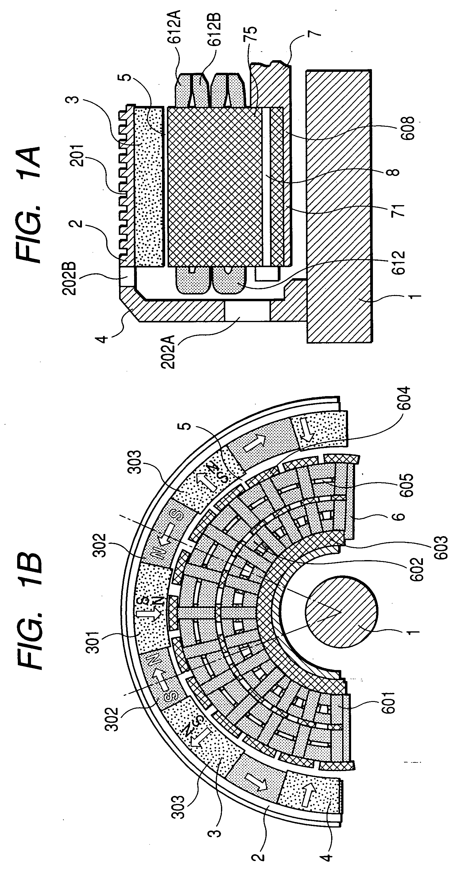
[0041]FIG. 2A is an axial half sectional view of an outer-rotor type wheel-in motor for use in an electric wheel according to a second embodiment of the invention. FIG. 2B is a half front view of this wheel-in motor when viewed from the right side in FIG. 2A.

[0042] In the second embodiment, unlike the first embodiment, the back core part 603 and the tooth pieces 604 are separated from each other, and the back core part 603 is provided on the rotor 4 side such that it faces the electric gap 502. More specifically, an annular part 606 extending in the axial direction is provided in the disk part of the bowl-shape member 2, and the back core part 603 is fixed to the annular part 606.

[0043] In the second embodiment, the tooth pieces 604 and the coils of the three-phase winding 602 of the armature 6 are bonded by an adhesive support 607 having good heat-conductivity to form the armature 6 in the shape of a cylinder. The coils of the three-phase winding can be wound around each of the t...

third embodiment

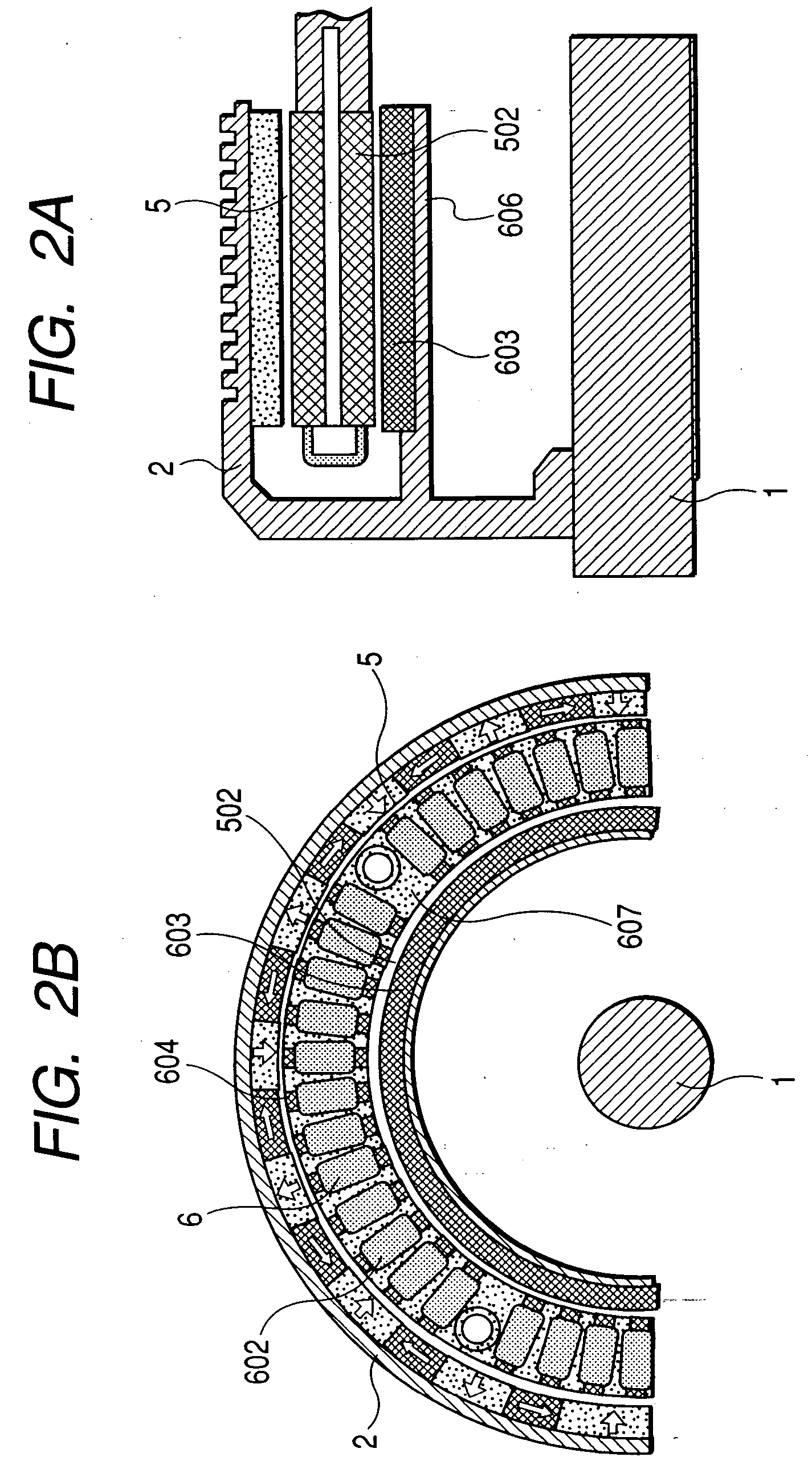
[0045]FIG. 3A is an axial half sectional view of an outer-rotor type wheel-in motor for use in an electric wheel according to a third embodiment of the invention. FIG. 3B is a half front view of this wheel-in motor when viewed from the right side in FIG. 3A.

[0046] The third embodiment is different from the second embodiment in that the back core part 603 is replaced by a magnet-type field generator 2b in the shape of a cylinder constituted by magnets arranged in the Halbach array. The magnet-type field generator 2b is fixed to an annular part 608 similar to the annular part 606 explained in the second embodiment. Since the magnet-type field generator 2b is applied with centrifugal force, the magnet type field generator 2b is covered by a ring member made of non-magnetic or magnetically saturated material for the purpose of mechanical protection. Radiating fins similar to the radiating fins 201 explained in the first embodiment are provided in the inner surface of the annular part 6...


PUM


Abstract

The rotor of the outer-rotor type wheel-in motor of the electric wheel includes a field generator facing the outer surface of the stator across from an electrical gap. The field generator includes pole magnets magnetized in the radial direction with respect to the rotation axis of the wheel-in motor,- adjacent two of the-pole magnets having opposite directions of magnetization so that magnet polarity of the field generator alternates at a predetermined pole pitch along the circumferential direction, yoke magnets magnetized in the circumferential direction each of which is put between corresponding adjacent two of the pole magnets to strengthen magnetic field formed by the pole magnets, and a field generator support member to which the field generator is fixed, the field generator support member being fixed to the rotary shaft which is rotatably supported by a wheel suspension system of a vehicle.

Description

CROSS-REFERENCE TO RELATED APPLICATION [0001] This application is related to Japanese Patent Application No. 2004-378251 filed on Dec. 27, 2004, the contents of which are hereby incorporated by reference. BACKGROUND OF THE INVENTION [0002] 1. Field of the Invention [0003] The present invention relates to an electric rotating machine usable as a wheel-in motor for automobiles. [0004] 2. Description of Related Art [0005] Recent years have seen a remarkable progress in electric motorization in automobile drive systems. In particular, much attention has focused on the “electric wheel”. In this specification, the term “electric wheel” refers to a wheel of an automobile in which whole or parts of a stator and a rotor of an electric rotating machine for driving the wheel are built in this wheel. [0006] Japanese Patent Application Laid-open No. 8-289501 proposes an inner-rotor type electric wheel in which a stator (armature) having a three-phase winding is disposed in a radially outer space...

Claims


Application Information

Patent Timeline
IPC IPC(8): B60K1/00H02K7/00H02K21/12H02K1/22
CPCB60K7/0007B60K17/043B60K2007/003B60K2007/0038B60K2007/0061B60L2220/46H02K7/14H02K21/12H02K21/22Y02T10/641B60L2220/44B60L2220/50Y02T10/64
Inventor KUSASE, SHINMUKAI, TAKUZOU
Owner DENSO CORP
Why Eureka
Try Eureka