Control input device with vibrating function

a technology of input device and function, which is applied in the direction of instruments, surveying and navigation, navigation instruments, etc., can solve the problems of operator inability to look at the display screen for safety reasons, and cannot recognize the degree of forwarding of playback objects

Active Publication Date: 2006-07-06
ALPINE ELECTRONICS INC
View PDF7 Cites 93 Cited by
  • Summary
  • Abstract
  • Description
  • Claims
  • Application Information

AI Technical Summary

Benefits of technology

[0011] The present invention is made in view of such problems. Accordingly, it is an object of the invention to provide a control input device with a vibrating function that allows an operator to recognize a change in the state of a control object after a long key press is confirmed.

Problems solved by technology

However, the operator has to actually see or hear the information.
At the time of playing back music by an audio system such as a CD player, when the operator performs an operation to speed up the playback action (e.g., FWD (fast-forward) key operation), the operator cannot recognize the degree of forwarding of the playback object even when he / she can recognize that the key has been pressed by the vibration.
However, when the system is for vehicles and the operator is driving a car, the operator cannot look at the display screen for safety reasons.
This therefore poses the problem of determining when the music has been changed to the desired music after a long key press.

Method used


Image

  • Control input device with vibrating function
  • Control input device with vibrating function
  • Control input device with vibrating function

Examples


first embodiment

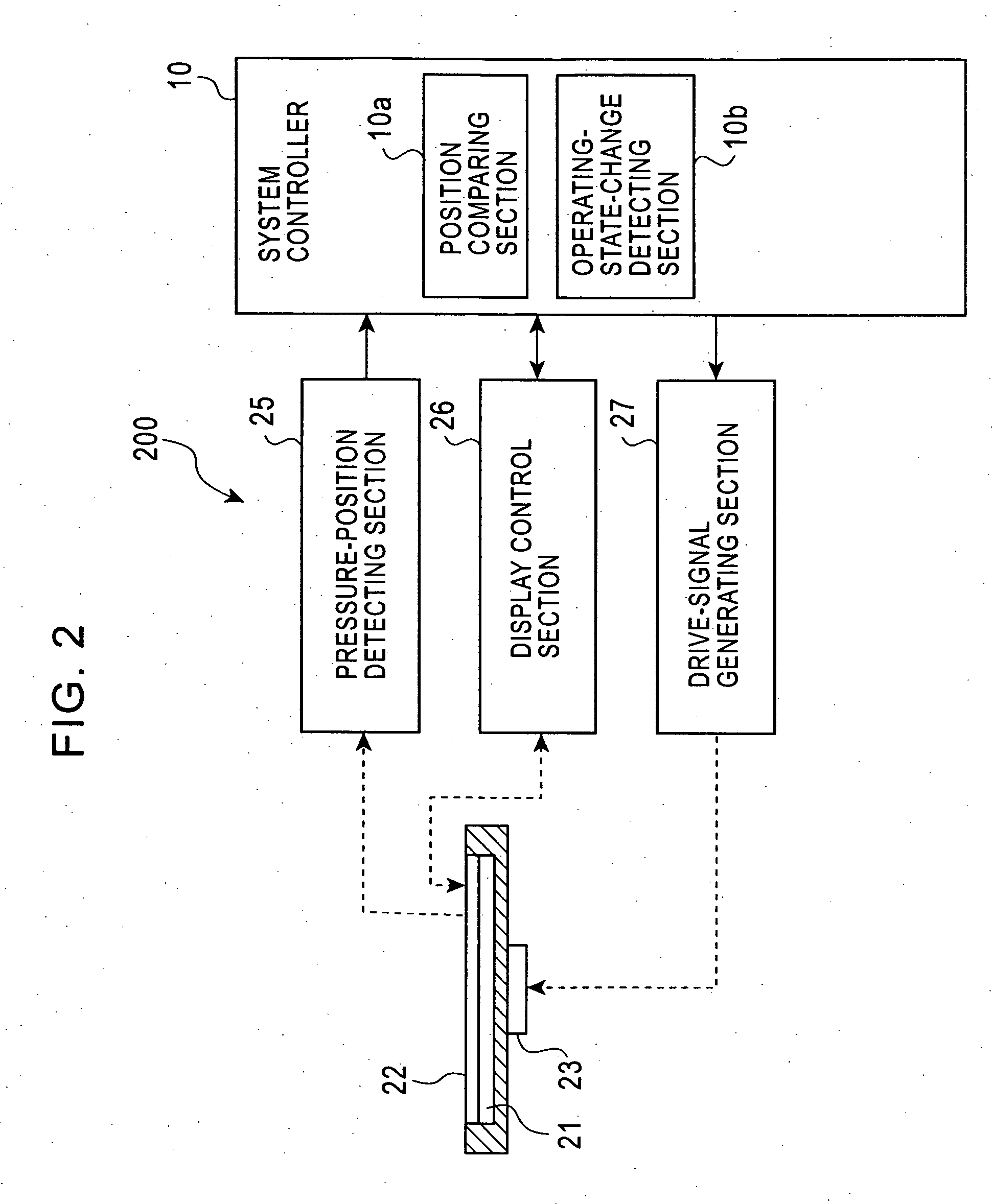
[0047]FIG. 2 is a functional block diagram of a control input system 200 with a vibration function according to a first embodiment of the invention.

[0048] As shown in FIG. 2, the vibration-function-equipped control input system 200 includes a pressure-position detecting section 25 that produces a detection signal depending on the position of the touch panel 22 pressed; a display control section 26 that allows the liquid-crystal panel 21 to display a control screen and obtains the position of a control key displayed on the control screen; and a drive-signal generating section 27 that generates vibration to be applied to the vibration unit 23.

[0049] The system controller 10 includes a position comparing section 10a that compares the position of the touch panel 22 pressed to the position of a control key displayed on the liquid-crystal panel 21; and an operating-state-change detecting section 10b that detects the change of music or the like to be controlled.

[0050] The display unit 2...

second embodiment

[0087] A vibration-function-equipped control input system 200a according to a second embodiment of the invention will be described hereinbelow.

[0088] The second embodiment is different from the first embodiment in that the control object is a finite value that varies gradually and has a reference point being a higher limit, a lower limit, or a median. When the sound level has passed through the reference point, the touch panel is vibrated.

[0089]FIG. 7 is a functional block diagram of a vibration-function-equipped control input system 200a according to the second embodiment. This embodiment is also an application of the invention to the car-mounted navigation and AV system 100. The difference between the second embodiment and the first embodiment is that a system controller 10A has a reference-point-passage detecting section (control section) 10c. The other structure and operation (function) are basically the same as those of the first embodiment. Accordingly, the same components i...

third embodiment

[0115] A vibration-function-equipped control input system 200b according to a third embodiment of the invention will be described hereinbelow.

[0116] The third embodiment is different from the first and second embodiments in that the control object is field intensity when receiving FM broadcasting and so on; and the touch panel is vibrated when the field intensity has reached a predefined value.

[0117]FIG. 11 is a functional block diagram of a vibration-function-equipped control input system 200b according to the third embodiment. This embodiment is also an application of the invention to the car-mounted navigation and AV system 100. The difference between this embodiment and the first and second embodiments is that a system controller 10B has a field-intensity detecting section (control section) 10d. The other structure and operation (functions) are basically the same as those of the first embodiment. Accordingly, the same components in FIG. 10 as those of FIG. 2 are given the same...


PUM


Abstract

A vibration-function-equipped control input system includes: a display panel capable of displaying a control screen; a touch panel; a pressure-position detector; a vibration section that generates vibration to apply to the touch panel; and a controller operatively connected to the display panel, the touch panel, the pressure-position detector, and the vibration section. The controller directs the vibration section to generate a vibration of a first vibration pattern when a predetermined time has passed after the part of the touch panel corresponding to the position of a control key displayed on the control screen is pushed, and subsequently directs the vibration section to generate a vibration of a second vibration pattern when a change of a control object controlled by the control key is detected after the predetermined time has passed.

Description

BACKGROUND OF THE INVENTION [0001] 1. Field of the Invention [0002] The present invention relates to a control input device, and in particular, it relates to a control input device having the function of generating vibration in response to the operation of an operator. [0003] 2. Description of the Related Art [0004] Intuitive touch panels have recently been used as input devices for car-mounted navigation systems. In this type of car-mounted navigation systems, the user can control the navigation system by touching a screen (touch panel) on which a map is displayed. The operator can also control an audio-video (AV) system by touching the screen (touch panel) on which an AV control screen is displayed. For example, the user can perform operations such as playback, stop, and volume control by touching the control button on the screen on which a CD-player control screen is displayed. [0005] The operator can determine whether or not he / she has touched the control button on the touch pan...

Claims


Application Information

Patent Timeline
Patent Type & Authority Applications(United States)
IPC IPC(8): G09G5/00G06F3/0484G06F3/0487G06F3/0488
CPCG01C21/3652G06F3/011
Inventor KAJIMOTO, TOMOMITSUNOKAKE, YASUHARUISHIDA, SATOSHI
Owner ALPINE ELECTRONICS INC
Why Eureka
Try Eureka