Surge current detection device

a detection device and current technology, applied in the direction of instruments, emergency protective arrangements for limiting excess voltage/current, base element modifications, etc., can solve the problems of increasing the number of cases in which devices are damaged, the function of devices originally have may deteriorate, and the equipment in the facility may be damaged, etc., to achieve easy and correct detection, reduce size and cost, and simple structure

Inactive Publication Date: 2012-10-11
SANKOSHA CORP
View PDF7 Cites 3 Cited by
  • Summary
  • Abstract
  • Description
  • Claims
  • Application Information

AI Technical Summary

Benefits of technology

[0017]In other words, a first object of the present invention is to provide a surge current detection device enabling change in a state of orientation of magnetic powders due to a surge current entering a conductor to be viewed more clearly, and thus enabling easy and correct detection of a magnitude of a surge current value and the number of surge current entrances.
[0018]A second object of the present invention is to provide a surge current detection device that is free of a risk caused by Joule heat as opposed to the related art, is safe and has a simple structure, enables reduction in size and cost, and requires no large space for attachment.
[0019]A third object of the present invention is to provide a surge current detection device that can easily be attached to or detached from a conductor.

Problems solved by technology

In recent years, with improvement in quality of pieces of equipment such as communication circuits and power supply circuits, there is a trend of increasing a number of cases in which devices are damaged by, e.g., lightning.
If the surge current enters the inside of the facility, the pieces of equipment in the facility may be damaged.
In such protectors that serve to protect the pieces of equipment in the facilities from lightning surge current such as lightning, protective devices, which are lightning protection devices such as lightning protection tubes (i.e., arresters) and / or varisters included therein may also be damaged, and therefore, surge current detection devices that detect entrance of surge current are also required for protectors as in the facilities to be protected.
As a result of the deterioration, the functions that the devices originally have may deteriorate, and thus, it is important to change a deteriorated protector promptly.
However, the related art surge current detection devices described in Japanese Patent Laid-Open Nos. 2005-150657, 2006-244889 and 2007-242569 have problems (a) and (b) described below.
However, a surge current flows in a short period of time, and only a small amount of Joule heat is generated, resulting in a failure to provide favorable deterioration detection sensitivity.
(b) The device using a metal shrinkable material, etc., is a mechanical structure and thus, takes a lot of trouble in attaching the device to a conductor, and furthermore, is difficult to achieve reduction in size, weight and cost.
As described above, the related art surge current detection devices have the problems of a failure to provide favorable deterioration detection sensitivity, a lot of trouble taken in attaching the device to a conductor, and the difficulty of reduction in size, weight and cost.
However, a surge current such as lightning flows in an extremely short period of time, and thus, it is difficult to provide improved detection sensitivity.

Method used


Image

  • Surge current detection device
  • Surge current detection device
  • Surge current detection device

Examples


first embodiment

Configuration of First Embodiment

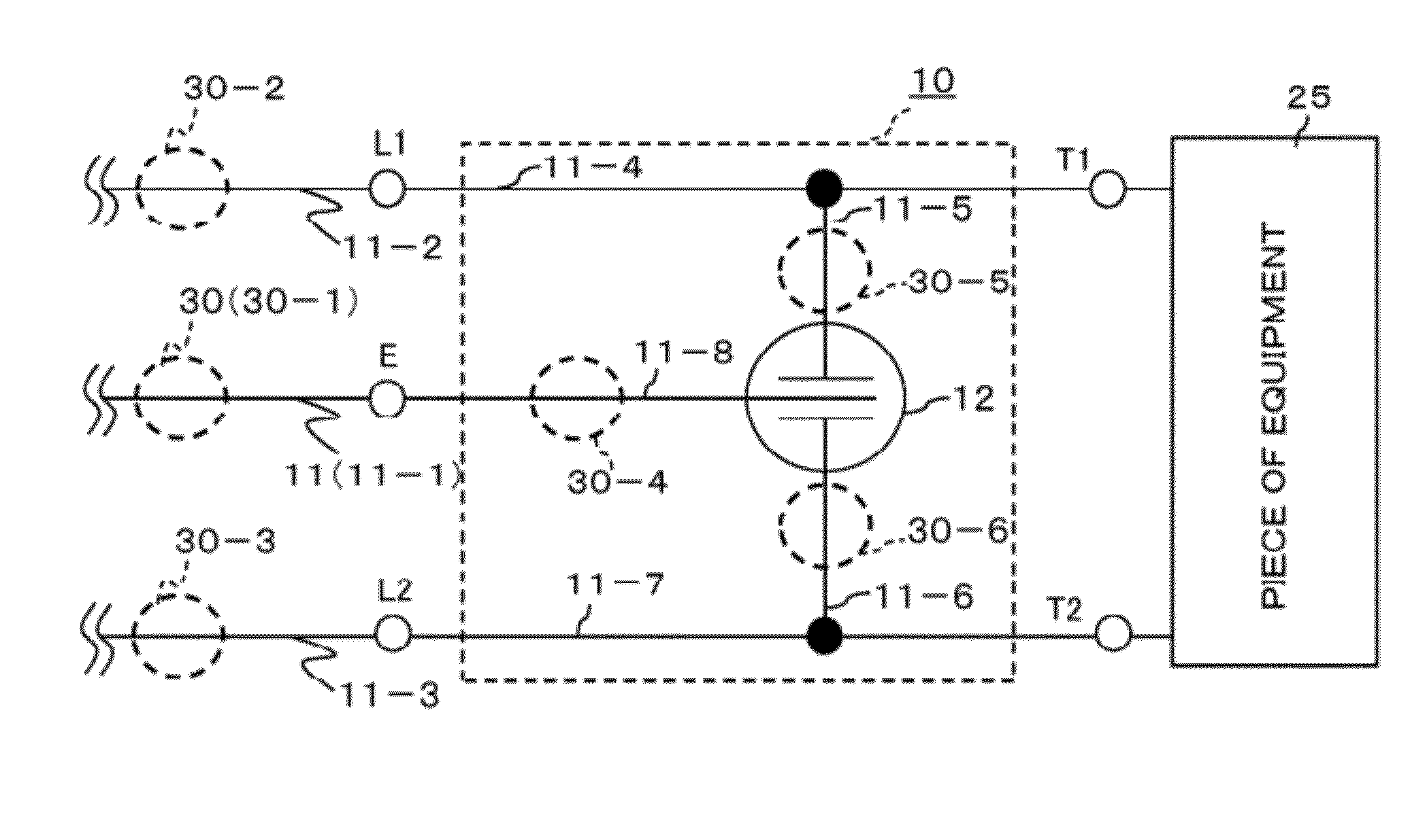
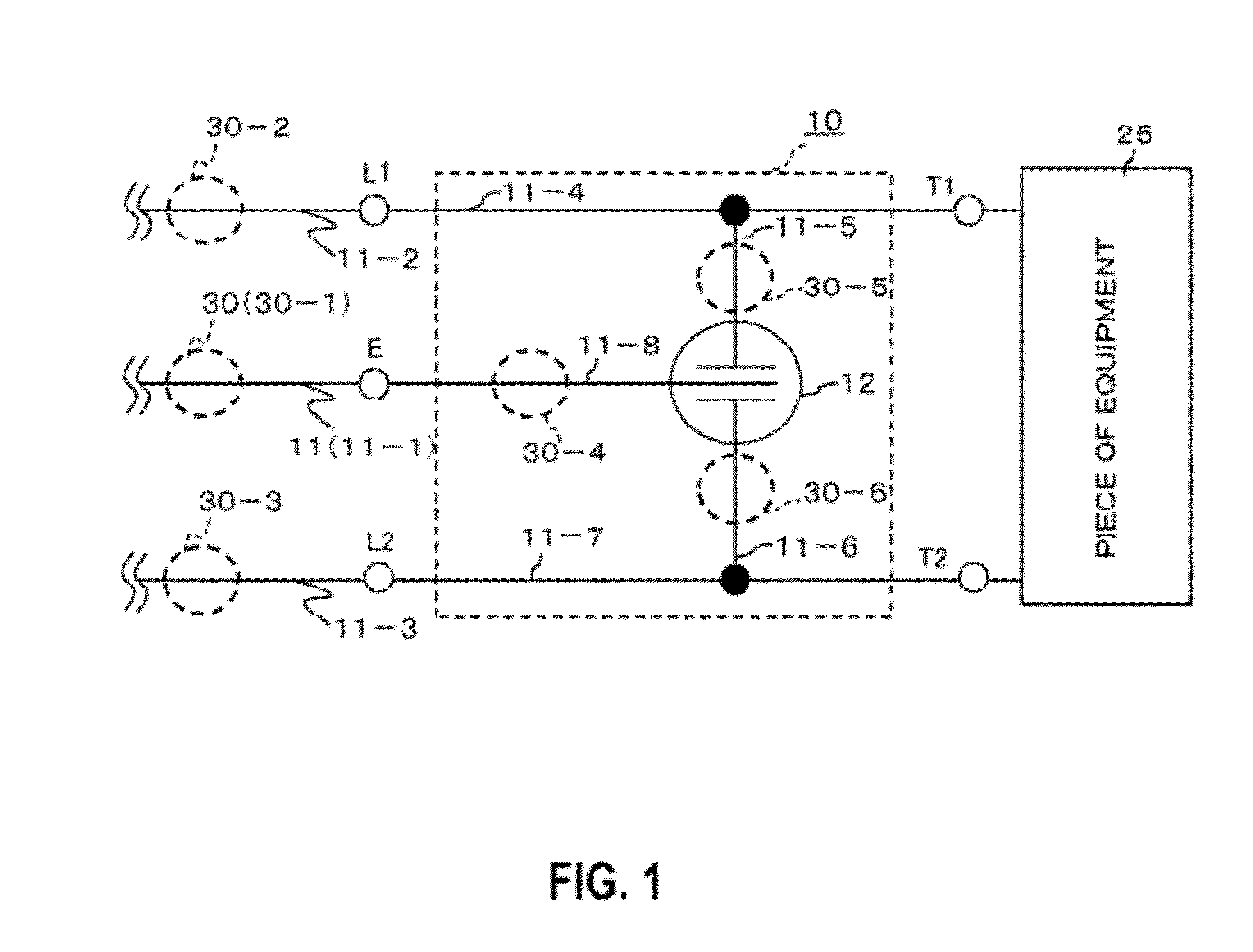
[0043]FIG. 1 is a circuit diagram illustrating a protector provided with surge current detection devices according to a first embodiment of the present invention.

[0044]As illustrated in FIG. 1, a protector 10 is intended to protect a piece of equipment 25 such as a communication apparatus from a surge current such as lightning, and includes an earth terminal E connected to a conductor 11 (for example, 11-1), which is a grounding wire, two line-side terminals L1 and L2 connected to two conductors 11-2 and 11-3, respectively, which are lines such as a communication wire and a power supply wire, and two equipment-side terminals T1 and T2 connected to the piece of equipment 25. The line-side terminal L1 and the equipment-side terminal T1 are connected via a conductor 11-4, and the line-side terminal L2 and the equipment-side terminal T2 are connected via a conductor 11-7.

[0045]A first electrode of a protective device (for example, a three-electrode arres...

second embodiment

Variations of First Embodiment and Second Embodiment

[0085]The present invention is not limited to the first embodiment and the second embodiment, and various modes of use and variations are possible. Examples of the modes of use and variations include those described in (i) to (iii) below.

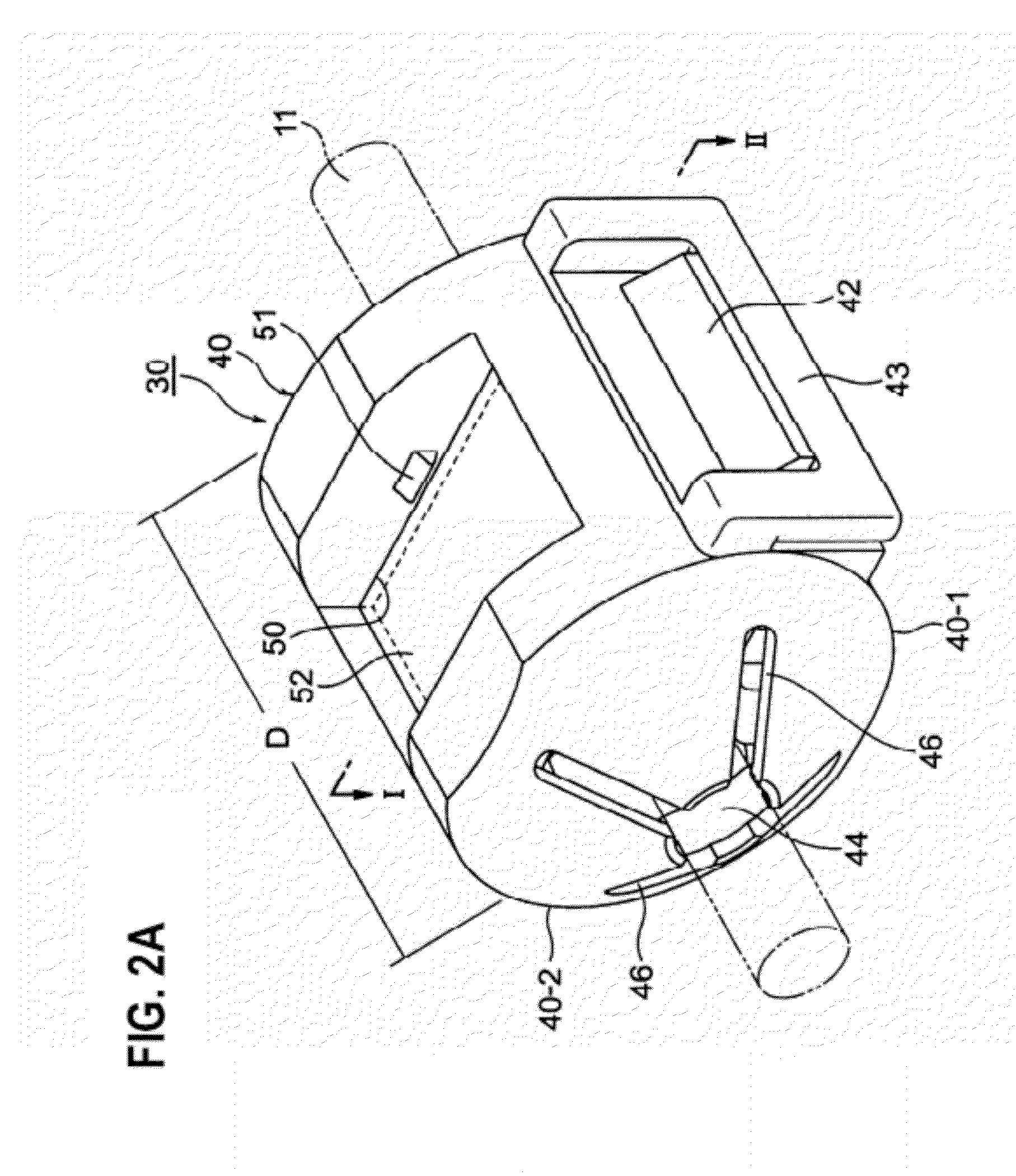
(i) The holder 40 or 40A for mounting the magnetic force concentrating member 60 and the magnetic material sheet 70 may be changed to have a shape and structure other than those illustrated in the drawings. For example, in FIGS. 2B and 7B, the hinge portion(s) 41-1 and 41-2 or 41 in the holder 40 or 40A are removed to separate the first holder body 40-1 or 40-1A and the second holder body 40-2 or 40-2A, and detachable fitting parts such as recesses and projections are provided at a part of connection between the first holder body 40-1 or 40A-1 and the second holder body 40-2 or 40-2A. With such configuration, a conductor 11 is held between the first holder body 40-1 or 40A-1 and the second holder b...


PUM


Abstract

A surge current detection device 30 is detachably attached to a conductor 11 and detects a surge current entering the conductor 11. The surge current detection device 30 includes: a holder 40 releasably holding the conductor 11 via first and second holder bodies 40-1 and 40-2 facing each other; a magnetic force concentrating member 60 having a substantially U-shaped cross-section, the magnetic force concentrating member 60 being secured inside the holder 40 and concentrating a magnetic flux included in a magnetic field generated by the surge current entering the magnetic flux conductor 11 to a high density at a predetermined detection region; and a magnetic material sheet 70 secured inside the holder 40 in such a manner that the magnetic material sheet 70 is positioned at the detection region, the magnetic material sheet 70 detecting the surge current.

Description

BACKGROUND ART[0001]1. Field of the Invention[0002]The present invention relates to a surge current detection device provided in, e.g., a protector for insulating (i.e., protecting) a piece of equipment such as a communication circuit or a power supply circuit from a surge current, for example lightning, entering a conductor such as a communication wire or a power supply wire connected to the piece of equipment, to detect a state of the entrance of the surge current, such as a magnitude thereof, and specifically relates to a surge current detection device that upon entrance of a surge current, detects a state of the entrance of the surge current, using a magnetic field generated on a conductor.[0003]2. Description of the Related Art[0004]In recent years, with improvement in quality of pieces of equipment such as communication circuits and power supply circuits, there is a trend of increasing a number of cases in which devices are damaged by, e.g., lightning. For example, where light...

Claims


Application Information

Patent Timeline
Patent Type & Authority Applications(United States)
IPC IPC(8): G01R1/20
CPCB82Y25/00G01R19/04H01F2017/065G02B26/026G01R15/148G01R33/0385
Inventor OKAWA, TAKAYUKISAEKI, HIDEYOSHIOUCHI, TAKUYA
Owner SANKOSHA CORP
Why Eureka
Try Eureka