Heat Exchangers for Boilers

A technology of heat exchangers and condensing boilers, applied in heat exchange equipment, heat exchangers, water heaters, etc., can solve the problems of not explaining the method of production or installation, difficult to produce, etc.

Active Publication Date: 2021-07-06
اريستون ثيرمو اس بي ايه +1
View PDF10 Cites 0 Cited by
  • Summary
  • Abstract
  • Description
  • Claims
  • Application Information

AI Technical Summary

Problems solved by technology

[0027] It is difficult to produce said disc, possibly made of refractory material, since a coil connecti...

Method used


Image

  • Heat Exchangers for Boilers
  • Heat Exchangers for Boilers
  • Heat Exchangers for Boilers

Examples


Embodiment Construction

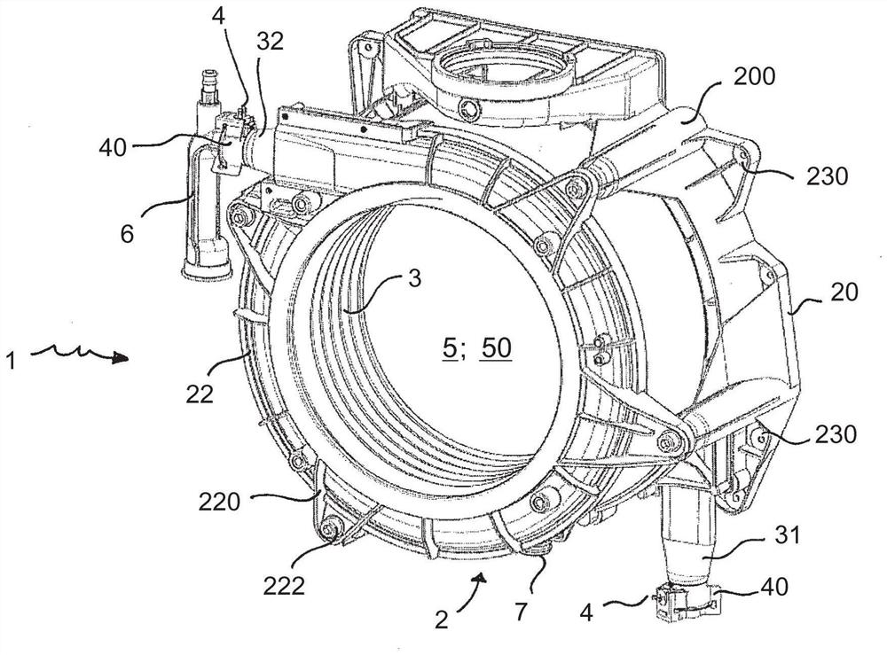
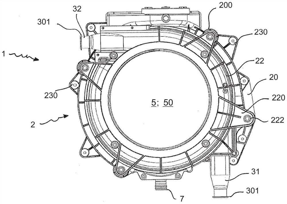
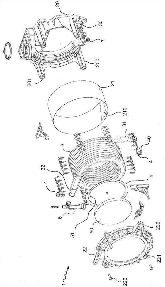
[0044] The heat exchanger 1 , hereinafter referred to simply as the exchanger 1 , comprises a suitable vessel body 2 , at least one coil and at least one temperature sensor device 4 .

[0045] The term "coil" means a bundle 3 of tubes, preferably metallic, wound helically around a central axis, adapted to form a suitable number of turns, and delimiting a combustion chamber 300 in which the combustion chamber 300 is introduced. Smoke produced by a device (not shown).

[0046] Said coil is advantageously made as a single piece, ie it is defined by a seamless single element.

[0047] Consequently, the coil has no welds and / or joints; this favors a uniform and homogeneous deformation due to the temperatures it is subjected to.

[0048] The coil is provided with at least a first end 31 serving as an inlet for a heat transfer fluid to be heated and at least a second end 32 serving as an outlet for said heat transfer fluid .

[0049] According to a preferred variant, said coil has...


PUM


Abstract

Heat exchanger (1) for a gas-fired condensing boiler, provided with a suitable vessel body (2), at least one tube bundle (3), at least one temperature sensor device (4), wherein said tube bundle (3) is surrounded by tubes in the center The axis is helically wound, suitable to form a suitable number of turns delimiting the combustion chamber (300), and provided with a first end (31) serving as an inlet for a heat transfer fluid to be heated and a first end (31) serving as an outlet for said heat transfer fluid Second end (32), wherein: - said exchanger (1) is provided with a partition (5) adapted to divide the combustion chamber (300) into a first sensitive chamber (310) and a second condensing chamber (320) ; characterized in that - said spacer (5) comprises a disc-shaped element with an outer contour (51) with a helical pattern, which is provided with a layer (50) of insulating material; - said spacer (5) can be The turns of the tube bundle (3) are screwed in order to adjust and change the size of the first sensitive chamber (310) and the second condensation chamber (320).

Description

technical field [0001] The present invention relates to heat exchangers for boilers or the like. [0002] Thus, the present invention belongs to the field of high yield heat generators (yield (referred to as low calorific value) in the range of 95-100%), in particular for room heating and / or domestic hot water production condensing boiler. Background technique [0003] Generally, a boiler is a device in which the water to be heated (for sanitary purposes and room heating) passes through a heat exchanger cooperating with a gas burner. [0004] The gas burner may comprise a tube bundle, preferably helically wound, the tube bundle being the turns through which the combustion gases or smoke produced by the gas burner pass to transfer heat to the gas passing through it. water. [0005] The combustion gases are exhausted to the outside of the exchanger and gas boiler after transferring their heat, including the potential heat of condensation, to the water. [0006] The boilers...

Claims


Application Information

Patent Timeline
IPC IPC(8): F24H1/43F24H9/02F28D7/02F28D21/00
CPCF24H1/16F24H9/1809F24H9/2007F28D7/02F24H1/43F28D7/024F28D21/0007F24H8/00Y02B30/00F28F1/025B21D53/027
Inventor B·巴姆波兹F·恰维蒂R·普恰瑞利C·斯普利
Owner اريستون ثيرمو اس بي ايه
Why Eureka
Try Eureka