Fastener

Active Publication Date: 2006-09-21
ILLINOIS TOOL WORKS INC
View PDF6 Cites 17 Cited by
  • Summary
  • Abstract
  • Description
  • Claims
  • Application Information

AI Technical Summary

Benefits of technology

[0014] An advantage of the present invention is providing a snap-fit fastener that is easily attached and easily detached, while providing a high retention force.
[0015] Another advantage of the present invention is providing a sna

Problems solved by technology

However, disassembly of a bolt and nut fastener is time consuming and sometimes problematic in that the removed nut can be dropped or misplaced, requiring that a spare nut be available for use.
The nut increases cost, assembly time and sometimes requires the use of specialized tools.
A disadvantage of such fasteners is that the fastener can be difficult to remove.
In som

Method used


Image

  • Fastener
  • Fastener
  • Fastener

Examples


Embodiment Construction

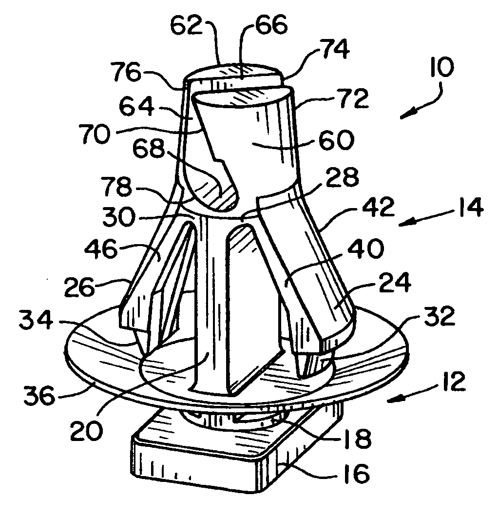
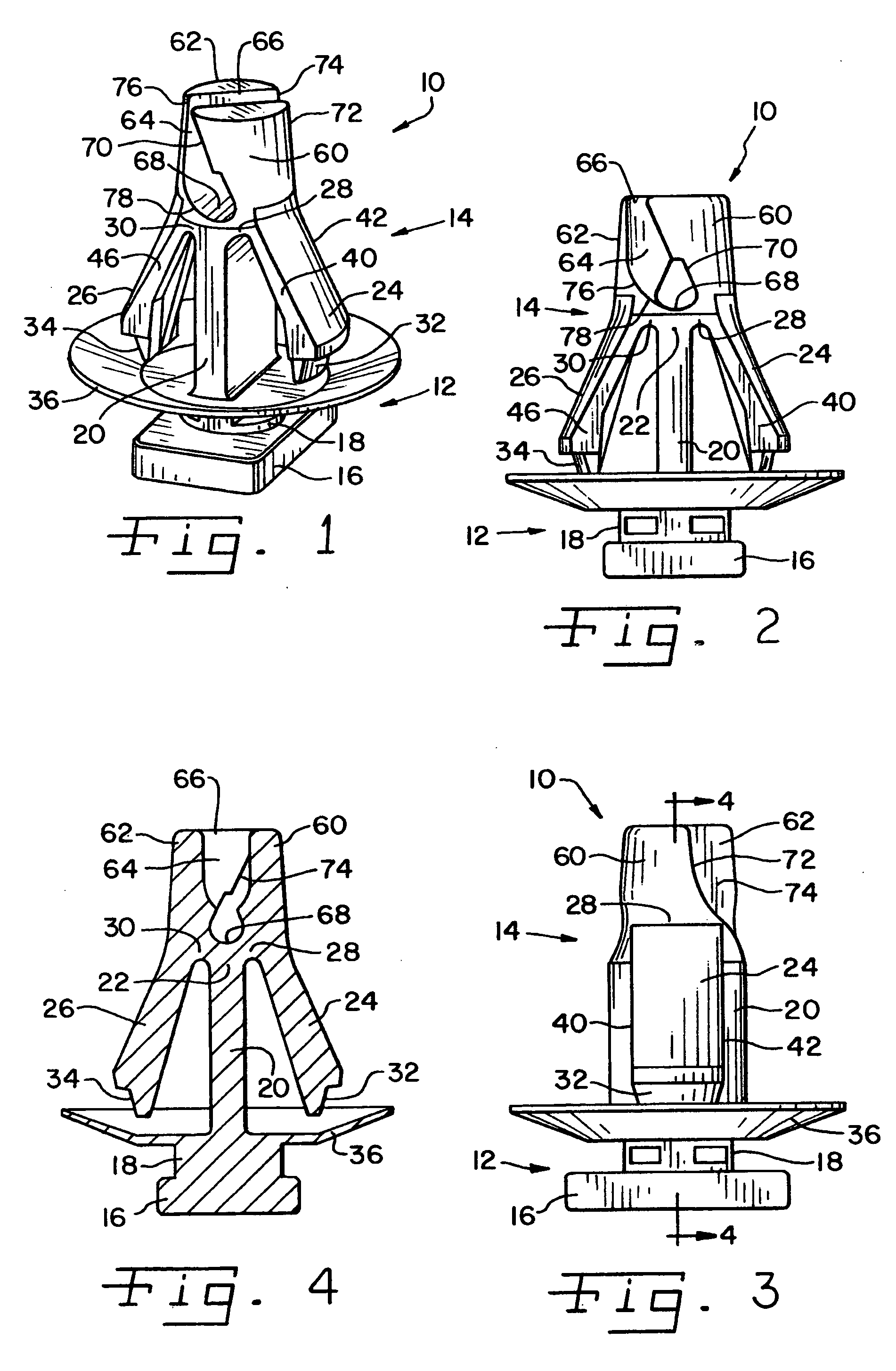
[0026] Referring now more specifically to the drawings and to FIG. 1 in particular, numeral 10 designates a fastener in accordance with the present invention. Fastener 10 is configured for securing one part or component (not shown) such as an automobile molding to a second part or component (not shown) such as an automobile body. Accordingly, fastener 10 includes an anchor portion 12 for connection to one of the components and a connecting portion 14 for attachment to the other component. It should be understood that the general size and shape can vary for the particular application of the present fastener without departing from the scope of the present invention.

[0027] In the exemplary embodiment shown, anchor portion 12 includes a head 16 and a neck 18. Head 16 is rectangular, being longer in one direction than in another as can be seen from a comparison of FIG. 2 and FIG. 3. As such, anchor portion 12 can be secured in a slot, such as a keyhole slot or other suitable fixture. Fo...


PUM


Abstract

A snap-fit fastener having deflectable, diverging wings extending from a distal end of a pedestal is provided with lead-in extensions from the connection of each wing to the pedestal. The extensions define a slot therebetween and are curved relative to the wings. By inserting an implement such as a screwdriver in the slot and twisting the implement, the lead-in extensions are spread relative to each other and the wings are moved toward the pedestal to allow the fastener to be disconnected from an object.

Description

CROSS-REFERENCE TO RELATED APPLICATIONS [0001] The present regular United States Patent Application claims the benefit of United States Provisional Application Ser. No. 60 / 663,889 filed Mar. 21, 2005.FIELD OF THE INVENTION [0002] The present invention relates generally to fasteners, and more particularly to snap-fit fasteners made of plastic. BACKGROUND OF THE INVENTION [0003] Snap-fit plastic fasteners for securing one item or part to another in an assembly are used in many industries for many purposes. Such fasteners are known in a variety of shapes and configurations, and may have snap-fit connections to each component, interlocking engagement to one component, threaded engagement to one component or to a second fastener component and various other attachment configurations. [0004] It is known in automotive applications to have one or more components that are pre-assembled at one location and shipped to another location for assembly with one or more other components. The pre-asse...

Claims


Application Information

Patent Timeline
IPC IPC(8): E04F19/02
CPCY10T24/309F16B21/086
Inventor LEPPER, MARK
Owner ILLINOIS TOOL WORKS INC
Why Eureka
Try Eureka