Control apparatus for vehicle

a control apparatus and vehicle technology, applied in the direction of electrical control, hybrid vehicles, engine starters, etc., can solve the problems of difficult to intentionally release the fuel pressure of the low-pressure delivery pipe at the stop of the vehicle operation, and the fuel supply from the fuel tank may be subject to a great amount of heat, so as to prevent deterioration in emission performance and smooth start performan

Inactive Publication Date: 2006-09-21
TOYOTA JIDOSHA KK
View PDF14 Cites 46 Cited by
  • Summary
  • Abstract
  • Description
  • Claims
  • Application Information

AI Technical Summary

Benefits of technology

[0012] In view of the foregoing, an object of the present invention is to provide a control apparatus for a vehicle incorporating an internal combustion engine having a first fuel injection mechanism (in-cylinder injector) for injecting fuel into a cylinder and a second fuel injection mechanism (intake manifold injector) for injecting fuel into an intake manifold and / or an intake port and performing engine intermittent operation control, that ensures smooth starting performance and also prevents deterioration in emission performance at the time of engine start.
[0013] Another object of the present invention is to provide a control apparatus for a vehicle incorporating an internal combustion engine having an in-cylinder injector and an intake manifold injector and also incorporating another driving force source other than the internal combustion engine, that ensures smooth starting performance and also prevents deterioration in emission performance at the time of engine start.

Problems solved by technology

With this configuration, however, the fuel line has a complicated configuration in the vicinity of the internal combustion engine, and the fuel supplied from the fuel tank may be subjected to a great amount of heat from the engine block of the internal combustion engine.
As such, it has been pointed out that the fuel, when subjected to the great amount of heat from the engine block, may partially vaporize in the fuel line or a delivery pipe for supplying the fuel into the intake manifold injector, leading to occurrence of vapor lock.
Thus, although an electromagnetic relief valve for releasing pressure is arranged downstream of the in-cylinder injection (high-pressure) delivery pipe, it is difficult to intentionally release the fuel pressure of the low-pressure delivery pipe at the time of stop of operation of the vehicle.
This leads to poor oil tightness, and there may occur leakage of the fuel from the intake manifold fuel injection valve during stop of operation of the vehicle.
Such leakage of the fuel may lead to deterioration in emission performance at the time of next start of the engine.

Method used


Image

  • Control apparatus for vehicle
  • Control apparatus for vehicle
  • Control apparatus for vehicle

Examples


Embodiment Construction

[0046] Hereinafter, an embodiment of the present invention will be described in detail with reference to the drawings. In the drawings, the same or corresponding portions have the same reference characters allotted, and detailed description thereof will not be repeated in principle.

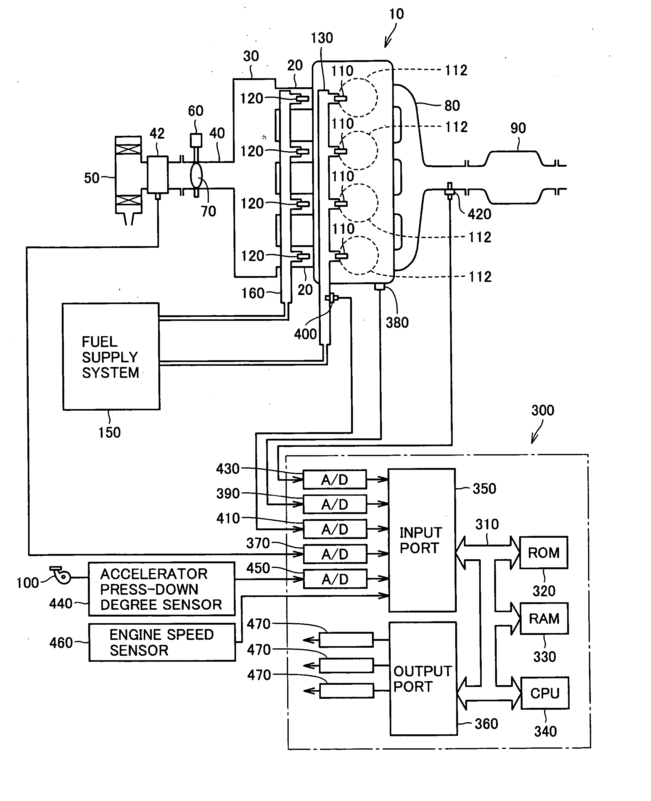
[0047]FIG. 1 schematically shows a configuration of an engine system provided with an internal combustion engine controlled by a control apparatus for a vehicle according to an embodiment of the present invention. Although an in-line 4-cylinder gasoline engine is shown in FIG. 1, application of the present invention is not restricted to the engine shown.

[0048] As shown in FIG. 1, the engine (internal combustion engine) 10 includes four cylinders 112, which are connected via corresponding intake manifolds 20 to a common surge tank 30. Surge tank 30 is connected via an intake duct 40 to an air cleaner 50. In intake duct 40, an airflow meter 42 and a throttle valve 70, which is driven by an electric motor ...


PUM


Abstract

In a vehicle incorporating an internal combustion engine having in-cylinder injectors and intake manifold injectors and performing engine intermittent operation control, at the end of vehicle operation, the fuel pressure is decreased in both a high-pressure delivery pipe and a low-pressure delivery pipe by actuation (opening) of an electromagnetic relief valve and by stop of operation of a low-pressure fuel pump. This prevents deterioration in emission performance at the next engine start attributable to fuel leakage due to degradation in oil tightness of the injectors during the operation stop period. When the engine is temporarily stopped by engine intermittent operation control, while the low-pressure fuel pump is stopped, actuation (opening) of the electromagnetic relief valve is prohibited. At the engine restart after temporary stop, the fuel in the high-pressure delivery pipe having its pressure secured at a certain level is injected to quickly start the engine.

Description

[0001] This nonprovisional application is based on Japanese Patent Application No. 2005-078389 filed with the Japan Patent Office on Mar. 18, 2005, the entire contents of which are hereby incorporated by reference. BACKGROUND OF THE INVENTION [0002] 1. Field of the Invention [0003] The present invention relates to a control apparatus for a vehicle, and more particularly to a control apparatus for a vehicle mounted with an internal combustion engine having a first fuel injection mechanism (in-cylinder injector) for injecting fuel into a cylinder and a second fuel injection mechanism (intake manifold injector) for injecting fuel into an intake manifold and / or an intake port. [0004] 2. Description of the Background Art [0005] A fuel injection apparatus provided with an in-cylinder injector for injecting fuel into a cylinder and an intake manifold injector for injecting fuel into an intake port, and controlling the in-cylinder injector and the intake manifold injector in accordance with...

Claims


Application Information

Patent Timeline
Patent Type & Authority Applications(United States)
IPC IPC(8): F02D41/30B60K6/00B60K6/445B60W10/06B60W10/18B60W10/26B60W20/00F02D29/02F02D41/06F02D41/34F02M51/00F02M55/02F02M63/00
CPCB60K6/445B60W10/06B60W20/00F02D41/042F02D41/064F02D41/3094F02D41/3836F02D2041/0095F02D2041/225F02D2041/3881F02D2200/0602F02D2200/0604F02D2200/503F02D2200/602F02D2250/02F02D2250/31F02M63/0225F02M63/029F02M69/046F02N11/0814Y02T10/6239Y02T10/62B60W10/30B60W2710/0616
Inventor YAMAGUCHI, KATSUHIKOINOUE, TOSHIOTOMATSURI, MAMORUHASEGAWA, KEIKOFUKUI, KEITA
Owner TOYOTA JIDOSHA KK
Why Eureka
Try Eureka