Method for applying torque overlay during split-mu braking conditions

a technology of torque overlay and split-mu braking, which is applied in the direction of brake systems, braking components, transportation and packaging, etc., can solve the problems of wheel slip and loss of traction, vehicle may have a tendency to spin out, and instability can be caused, so as to maintain vehicle stability

Active Publication Date: 2007-01-04
KELSEY HAYES CO
View PDF5 Cites 30 Cited by
  • Summary
  • Abstract
  • Description
  • Claims
  • Application Information

AI Technical Summary

Benefits of technology

[0012] The present invention provides the advantage of cooperatively utilizing braking controls from a slip control braking system and a torque overlay from a control assist steering system to provide stability control when traveling on a split-mu road surface. More importantly, a determination is made in response to steering wheel angle feedback of whether an aggressive braking strategy or non-aggressive split-mu braking strategy may be applied while maintaining vehicle stability. This is because steering wheel angle always precedes vehicle yaw due to the lag of the linkage and tires.

Problems solved by technology

Excessive wheel speed during vehicle acceleration may produce wheel slip and loss of traction.
Such instability can be caused during vehicle motion such as cornering.
One such instability condition in which VSC and control assist steering may work in cooperation with one another is when a vehicle is driving along a split-mu surface.
If however, the driver of the vehicle does not allow the control assist steering system to directionally correct the steering wheel angle, and if the high braking force is maintained on the front-left wheel, the vehicle may have a tendency to spin out.

Method used


Image

  • Method for applying torque overlay during split-mu braking conditions
  • Method for applying torque overlay during split-mu braking conditions
  • Method for applying torque overlay during split-mu braking conditions

Examples


Embodiment Construction

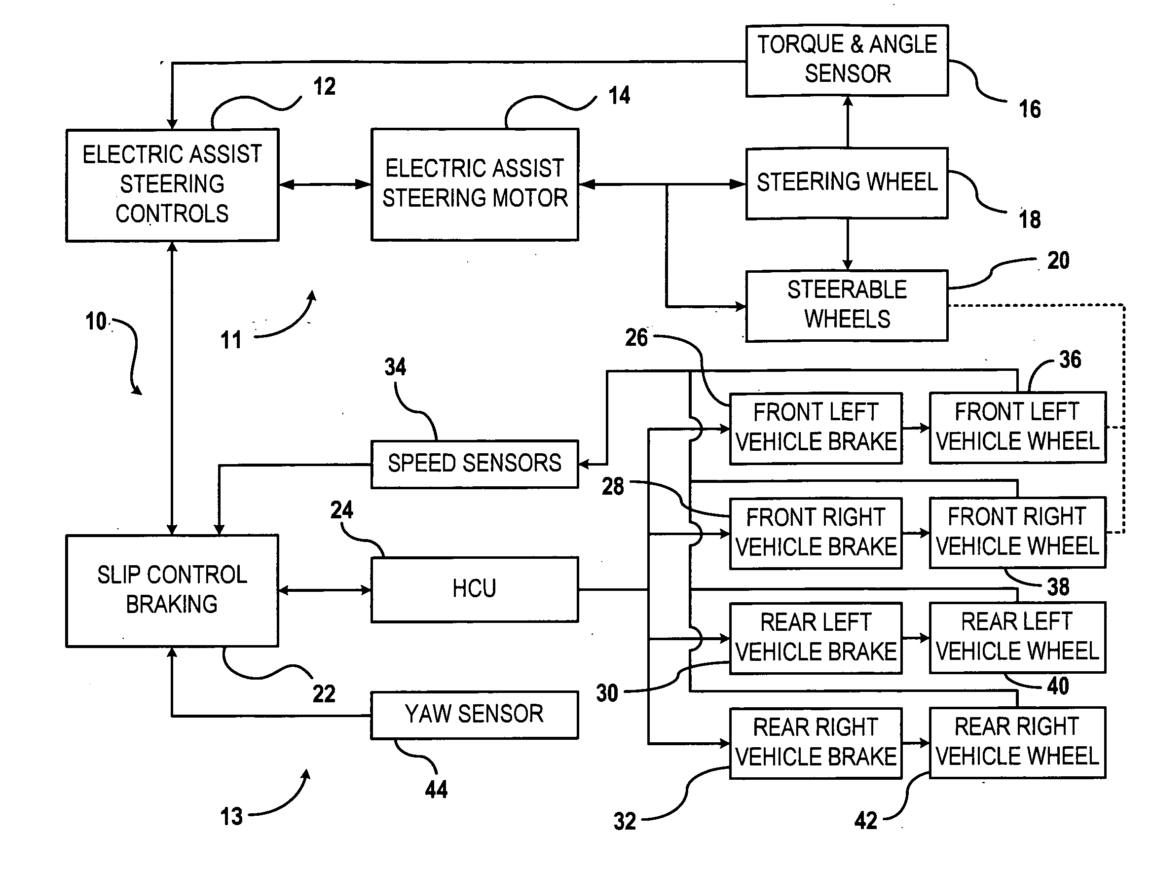
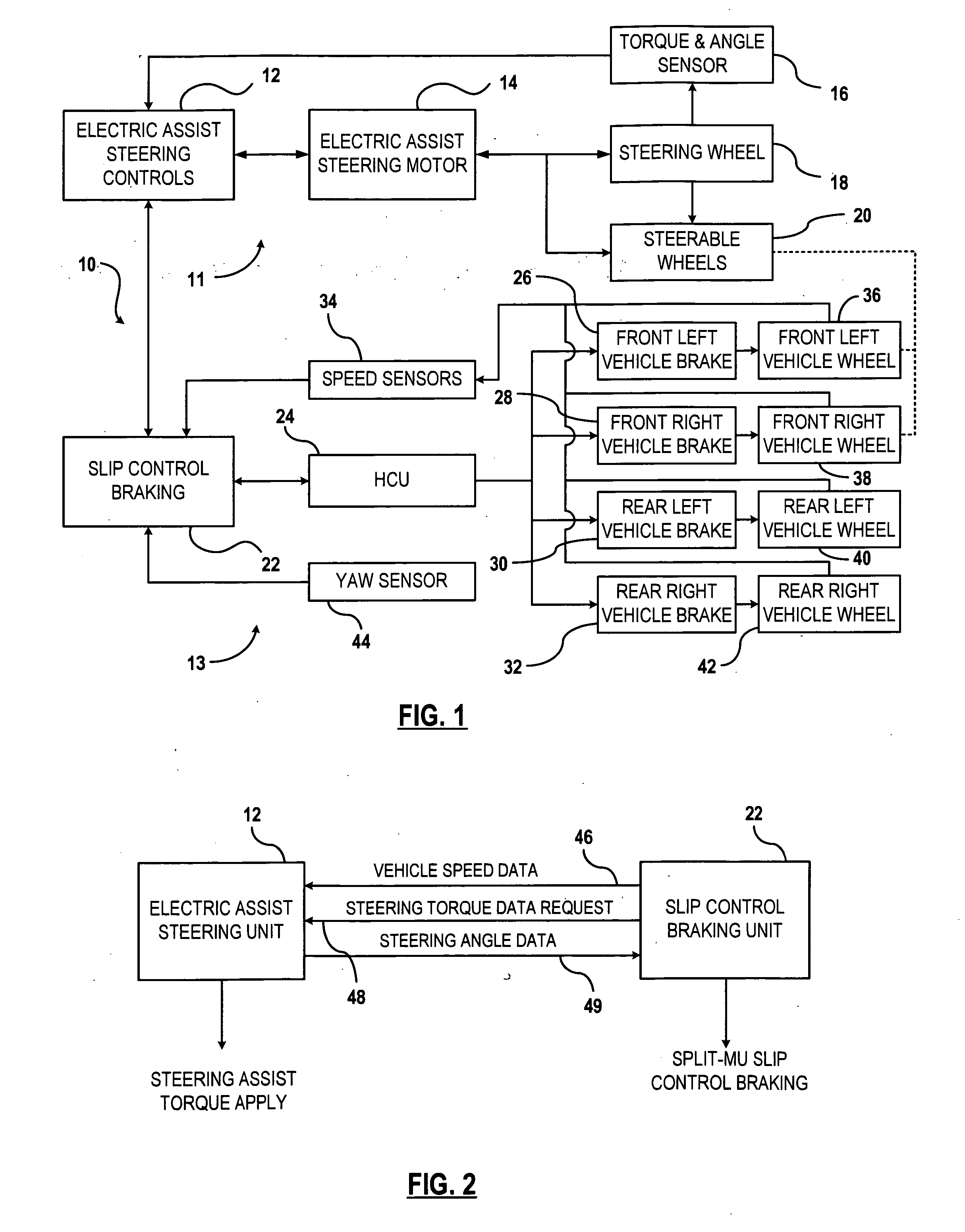
[0018]FIG. 1 is a schematic of an integrated vehicle stability control system 10 for controlling vehicle stability according to a first preferred embodiment of the present invention. The stability system 10 includes a steer-by-wire assist steering system 11 and slip control braking system 13. The steer-by-wire assist steering system 11 includes an electric assist steering control unit 12 for controlling the assisted steering torque generated by an electric assist steering motor 14. Alternatively, other types of steering assist devices may be used such as a device powered by hydraulic power or pneumatic power. The electric assist steering motor 14 is operatively coupled to a steering wheel 18 for providing steering assist torque to steerable wheels 20 of the vehicle.

[0019] The electric assist steering control unit 12 receives input data from a torque and angle sensor 16 for determining the present steering wheel angle and steering torque applied to the steering wheel 18. In response...


PUM


Abstract

A method is provided for vehicle stability control of a vehicle where the vehicle includes a slip control braking system that applies independent braking pressure to respective vehicle brakes of the vehicle. The vehicle further includes a steer-by-wire assist steering system for applying steering intervention for stability control. The method includes detecting a split-mu braking condition and applying a steering assist torque to the steering system. A determination is made whether a steering wheel angle condition is within a predetermined threshold. An aggressive braking strategy is applied if the steering wheel angle condition is within the predetermined threshold, else applying a non-aggressive braking strategy.

Description

CROSS REFERENCE TO RELATED APPLICATIONS [0001] Not Applicable. STATEMENT REGARDING FEDERALLY SPONSORED RESEARCH [0002] Not Applicable. BACKGROUND OF THE INVENTION [0003] 1. Field of the Invention [0004] The present invention relates to a vehicle stability control system, and more specifically, to an integrated system utilizing steering and braking controls. [0005] 2. Description of the Related Art [0006] Vehicle braking systems are known to include antilock braking (ABS), traction control (TC), and vehicle stability control (VSC). ABS systems monitor the wheel rotational behavior and selectively apply and relieve hydraulic brake fluid pressure in the respective vehicle brakes via electronically controlled isolation valves and dump valves for maintaining wheel speed within a selected slip range while maintaining optimum braking forces. Such controlled braking may be applied on an individual vehicle wheel, a combination of vehicle wheels, or to all vehicle wheels. [0007] In traction (...

Claims


Application Information

Patent Timeline
Patent Type & Authority Applications(United States)
IPC IPC(8): B60T8/60
CPCB60T8/1764B60T8/58B62D6/003B62D5/0472B60T2260/024
Inventor MILLER, JOE
Owner KELSEY HAYES CO
Why Eureka
Try Eureka