Planar loaded operably conformable material containment system

Inactive Publication Date: 2007-02-01
VENTURE CORE LLC
View PDF18 Cites 19 Cited by
  • Summary
  • Abstract
  • Description
  • Claims
  • Application Information

AI Technical Summary

Benefits of technology

[0016] This broad object of the invention can include particular embodiments of the material container invention which include a flexible layer having a square or rectangular body coupled on at least one of the opposed sides by a triangular end portion the vertices of which can be held in a first hand adjacent to one another to position a closure element to commence operation at the apex of the triangular end portion located proximate to the support surface. Another benefit of the triangular end portion can be to locate the closure element at an angle from the support surface between about ten degrees and about 45 degrees to accept a greater portion

Problems solved by technology

Everest expedition trail or comprises waste material being transported from the backyard to the local dump, containing and transporting the material poses a variety of problems familiar to the ordinary person.
One familiar problem related to containing and transporting material can be the difficulty of containing material amassed or accumulated on conventional tarpaulins or similar flexible sheets (“conventional tarpaulins”).
As to each of these varied devices and methods of containing or transporting material on an open or within a gathered conventional tarpaulin, there is a common problem in that no attempt to close the tarpaulin has been made or only a portion of periphery of the tarpaulin has been drawn upon or joined to contain the material loaded.
In any event, none of these devices or methods of containing material on or within a tarpaulin address the need of closing substantially the entirety of the periphery of the tarpaulin to decrease the transfer of material(s).
Another familiar problem with the use of conventional tarpaulins or other conventional devices which initially lay flat for loading and then alter configuration by coupling or joining portions of the periphery can be that a plurality of discrete closures must be operated to generate the closed condition of the device.
As such, these types of devices may be overly complex or incompatible with containing and transporting cargo or waste materials, or may not operate or may

Method used


Image

  • Planar loaded operably conformable material containment system
  • Planar loaded operably conformable material containment system
  • Planar loaded operably conformable material containment system

Examples


Example

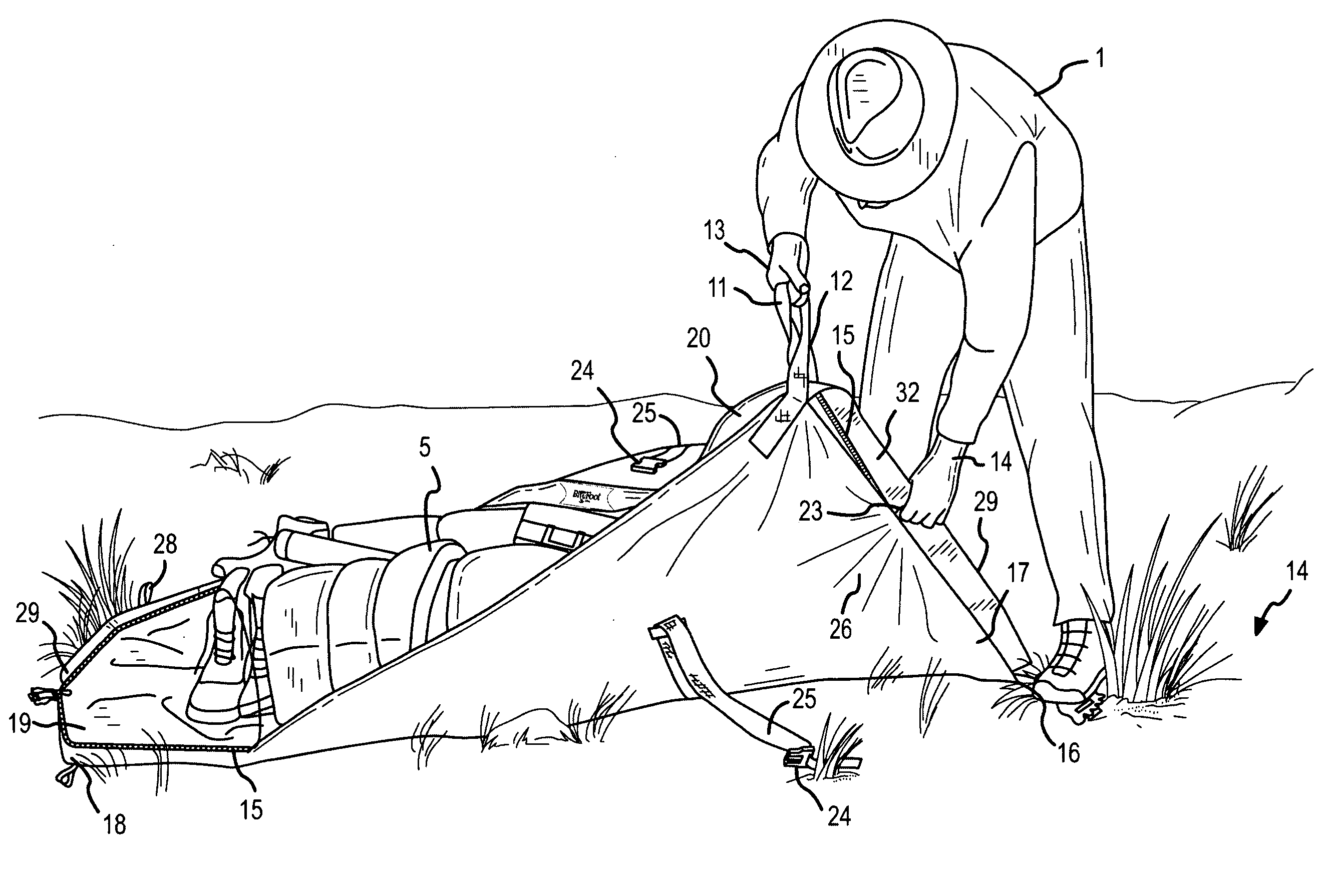
[0041] A material container which provides a flexible layer established in a substantially planar configuration on a support surface for loading material which operably conforms by closure to provide an enclosed space to contain the loaded material.

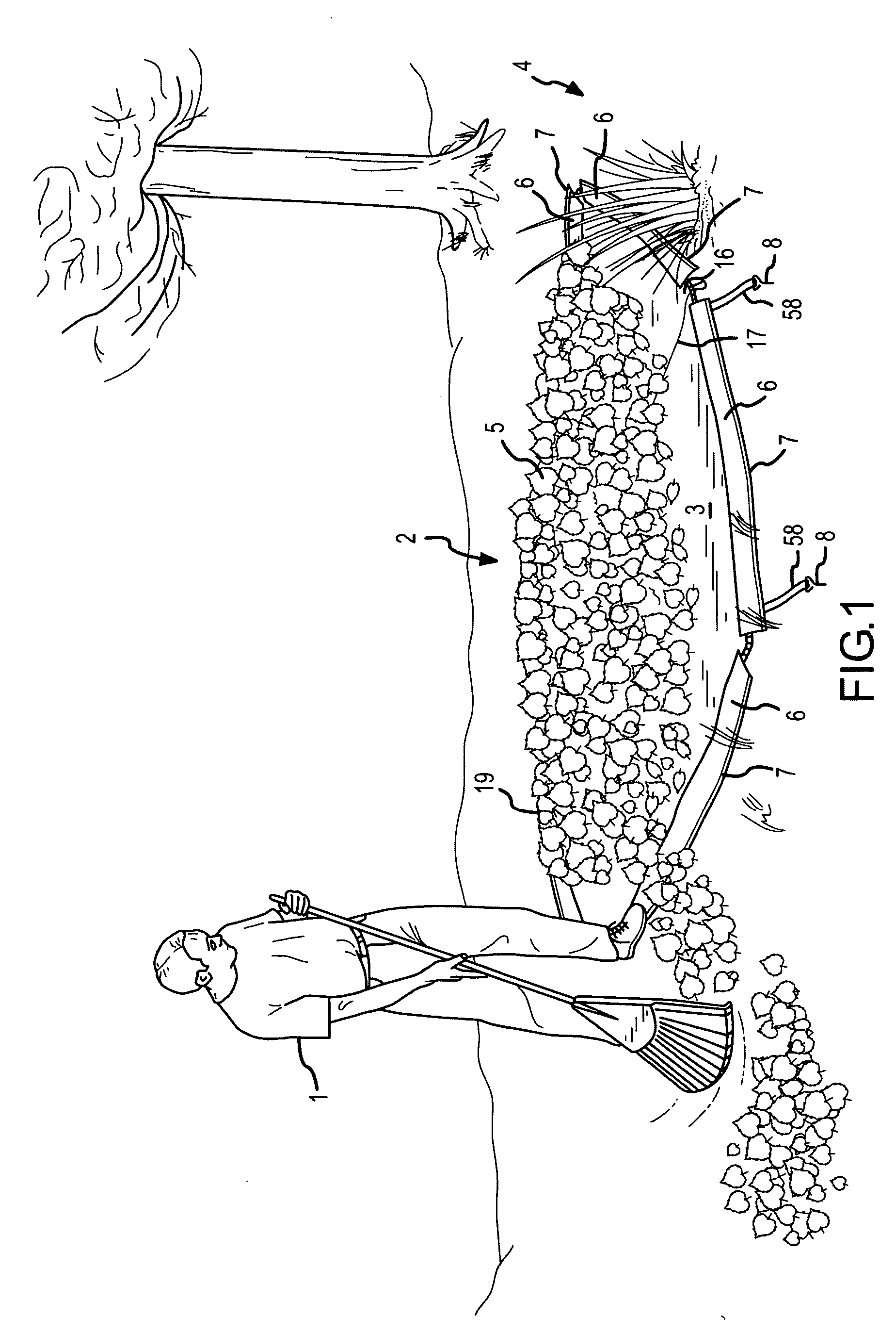
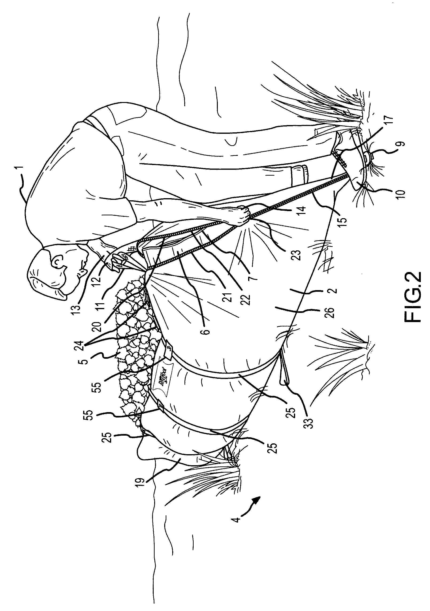
[0042] Now referring primarily to FIGS. 1 through 3, a method of using an embodiment of the material containment invention is shown. A person (1) can establish the material container (2) in a substantially planar configuration (3) on a support surface (4). A flap or a plurality of flaps (6) can be turned outward to secure the planar configuration (3) at a location on the support surface (4) by action of a securement element (7) such as an amount of weight contained in the flap or in one or more of the plurality of flaps. Separately, or in combination with an amount of weight (7) in the flap (7), the securement element (7) can comprise a stake or a plurality of stakes (8) tethered (58) to the flexible layer (26) or to the flap (6) and whi...


PUM


Abstract

A BigFoot™ Bag material containment system which provides a material container (2) having a flexible layer (26) which can be established in a substantially planar configuration (3) on a support surface (4) for loading material (5) and which operably conforms by closure (15) to provide an enclosed space (20) to contain the loaded material (5).

Description

I. BACKGROUND [0001] A BigFoot™ Bag material containment system which provides a flexible layer established in a substantially planar configuration on a support surface for loading material which conforms by operation of a closure to provide an enclosed space to contain the loaded material. [0002] Whether a material comprises valuable cargo being transported following the classic Mt. Everest expedition trail or comprises waste material being transported from the backyard to the local dump, containing and transporting the material poses a variety of problems familiar to the ordinary person. [0003] One familiar problem related to containing and transporting material can be the difficulty of containing material amassed or accumulated on conventional tarpaulins or similar flexible sheets (“conventional tarpaulins”). Because conventional tarpaulins can be laid flat for efficient loading of material(s), a numerous and wide variety of devices and methods have been developed to gather or se...

Claims


Application Information

Patent Timeline
IPC IPC(8): B65D30/00B65D33/06B65D33/00
CPCA45C3/00B65F2240/138B65F1/0006A45C13/002
Inventor SCHOENIG, DARRELL A.DOKTER, JAY D.
Owner VENTURE CORE LLC
Why Eureka
Try Eureka