
Tank and spout interface for heat exchanger and its manufacturing

Active Publication Date: 2013-10-03
HANON SYST
View PDF13 Cites 3 Cited by
  • Summary
  • Abstract
  • Description
  • Claims
  • Application Information

AI Technical Summary

Benefits of technology

The patent text describes a cooling mechanism for electronic components. The invention includes a tank part and a connecting part. The tank part has risers with a cross section shape of a circular section, which gradually decreases in height as they move away from the partition. This design helps to create an ideal flow pattern of the fluid and increases the flow rate. The connecting part has a smooth transition between the inner walls of the tank part and the tank part, thereby reducing pressure drop and improving efficiency. Overall, the invention provides a more effective cooling solution for electronic components.

Problems solved by technology

The drawback of these known connecting parts is that a pressure drop of the operating fluid occurs in them, which substantially influences the overall performance of the heat exchanger.

Method used


Image

  • Tank and spout interface for heat exchanger and its manufacturing
  • Tank and spout interface for heat exchanger and its manufacturing
  • Tank and spout interface for heat exchanger and its manufacturing

Examples


Embodiment Construction

[0021]The following detailed description and appended drawings describe and illustrate various exemplary embodiments of the invention. The description and drawings serve to enable one skilled in the art to make and use the invention, and are not intended to limit the scope of the invention in any manner.

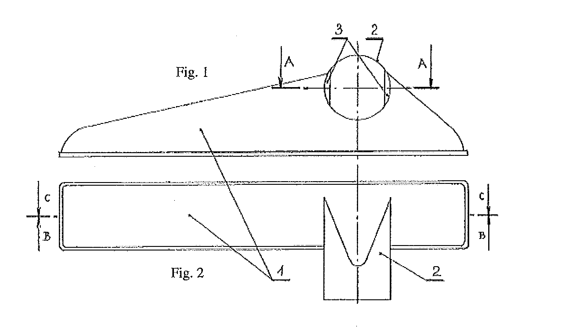
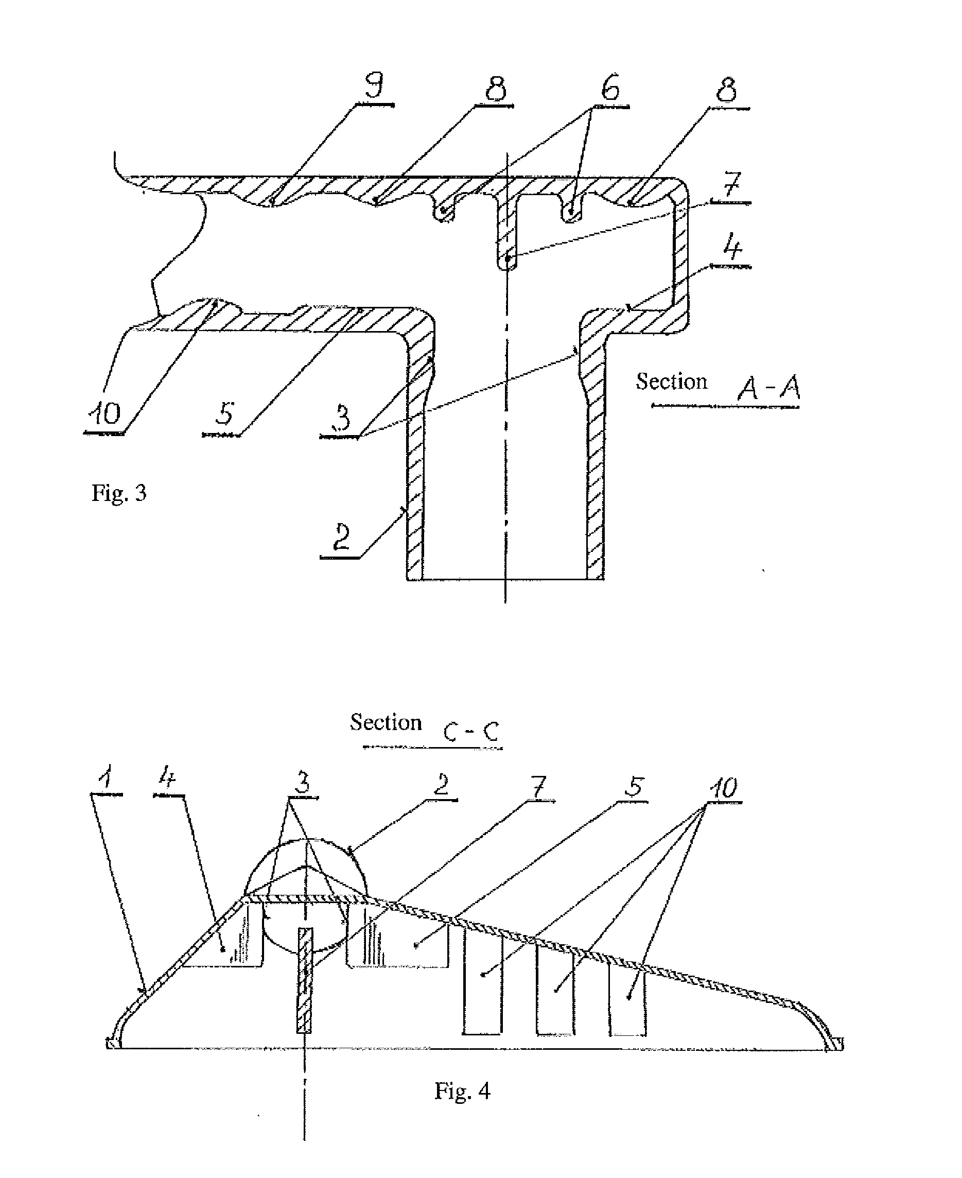
[0022]As can be seen from FIG. 1, the connecting part of a radiator according to this invention consists of a tank part 1, which is provided with a connection sleeve 2. The tank part 1 having in lengthwise section the shape of an obtuse-angled triangle. The connection sleeve 2 situated transversely in the region of the connecting line of the two legs of the obtuse-angled triangle has, situated at the places of its transition to the internal space of the tank part 1, two rounded longitudinal entry risers 3, narrowing the internal cross section of the connection sleeve 2. These longitudinal entry risers 3, oriented opposite each other and perpendicular to the outer margin of the tank p...


PUM


Abstract

A tank and spout interface of a radiator of a motor vehicle having a tank part having an inner surface, an outer surface, a connecting part, a bottom portion, a first end, a second end, a first outer margin, and a second outer margin. The tank and spout interface has a connection sleeve disposed on the tank part and extending outwardly from the tank part having an inner surface integrally formed with the inner surface of the first outer margin of the tank part and an outer surface integrally formed with the outer surface of the tank part. A first entry riser and a second entry riser are disposed on opposing sides of the inner surface of the connection sleeve and a first internal riser and a second internal riser are disposed on the first outer margin of the tank part.

Description

CROSS-REFERENCE TO RELATED APPLICATION[0001]This application claims priority to Czech Republic Patent Application Serial No. PV 2012-224 filed on Mar. 30, 2012, hereby incorporated herein by reference in its entirety.FIELD OF THE INVENTION[0002]The present disclosure relates to a connecting part of a radiator, specifically a radiator of a motor vehicle.BACKGROUND OF THE INVENTION[0003]This section provides background information related to the present disclosure which is not necessarily prior art. The connecting parts that are known for radiators of motor vehicles are formed by a plastic tank part. The plastic tank part has a width and length corresponding to the width and height of the radiator. Provided at the bottom of the tank part is a connection sleeve to supply and take away the operating fluid emerging into the internal space of the tank part.[0004]The drawback of these known connecting parts is that a pressure drop of the operating fluid occurs in them, which substantially ...

Claims


Application Information

Patent Timeline
IPC IPC(8): F16L5/00
CPCF16L5/00F28F9/0265F28F9/0263
Inventor KOLLAR, JAN GREGUSHRUZA, HYNEK
Owner HANON SYST
Learn More