Data erasing device using permanent magnet

a data eraser and permanent magnet technology, applied in the field of data erasers, can solve the problems of increasing disposal costs, increasing device size, and writing data in time, and achieve the effects of reducing the size and weight reducing the size of the magnetic shielding mechanism, and reducing the cost of the data eraser

Inactive Publication Date: 2007-03-01
KK TOSHIBA
View PDF9 Cites 16 Cited by
  • Summary
  • Abstract
  • Description
  • Claims
  • Application Information

AI Technical Summary

Benefits of technology

[0021] The data erasing device according to the present invention has an effect that the cost of the data erasing device can be decreased by decreasing the size of a magnet used in a magnetic circuit that generates an erasing magnetic field to be applied to the magnetic disk device to erase data, through application of the erasing magnetic field to the magnetic disk device from many directions, by decreasing the size and weight of the data erasing device, and by decreasing the size of a magnetic shielding mechanism that prevents magnetism from being leaked out to the outside.

Problems solved by technology

The method of writing random data on the entire surface of the magnetic disks of the hard disk device as described above has a problem in that writing the data takes time due to the large capacity of the hard disk device, and has an additional problem in that the disposal cost increases when a service organization is asked to erase the data.
On the other hand, in the data erasing device disclosed in U.S. Pat. No. 6,594,099 for erasing data by means of magnetic saturation, by passing the magnetic disk through a strong magnetic field, equipment for rotating the spindle motor is necessary, leading to the problem of an increase in the device size.
Also, there is a problem in that if, for some reason, the spindle motor does not rotate, the data will not be completely erased.
Consequently, the data erasing device becomes large and has increased weight.
Further, a magnetic shielding mechanism that prevents leakage of magnetism to the outside becomes large.
This results in high cost of the data erasing device.
However, data in a direction at a right angles to the direction of the external magnetic field cannot be easily demagnetized.

Method used


Image

  • Data erasing device using permanent magnet
  • Data erasing device using permanent magnet
  • Data erasing device using permanent magnet

Examples


first embodiment

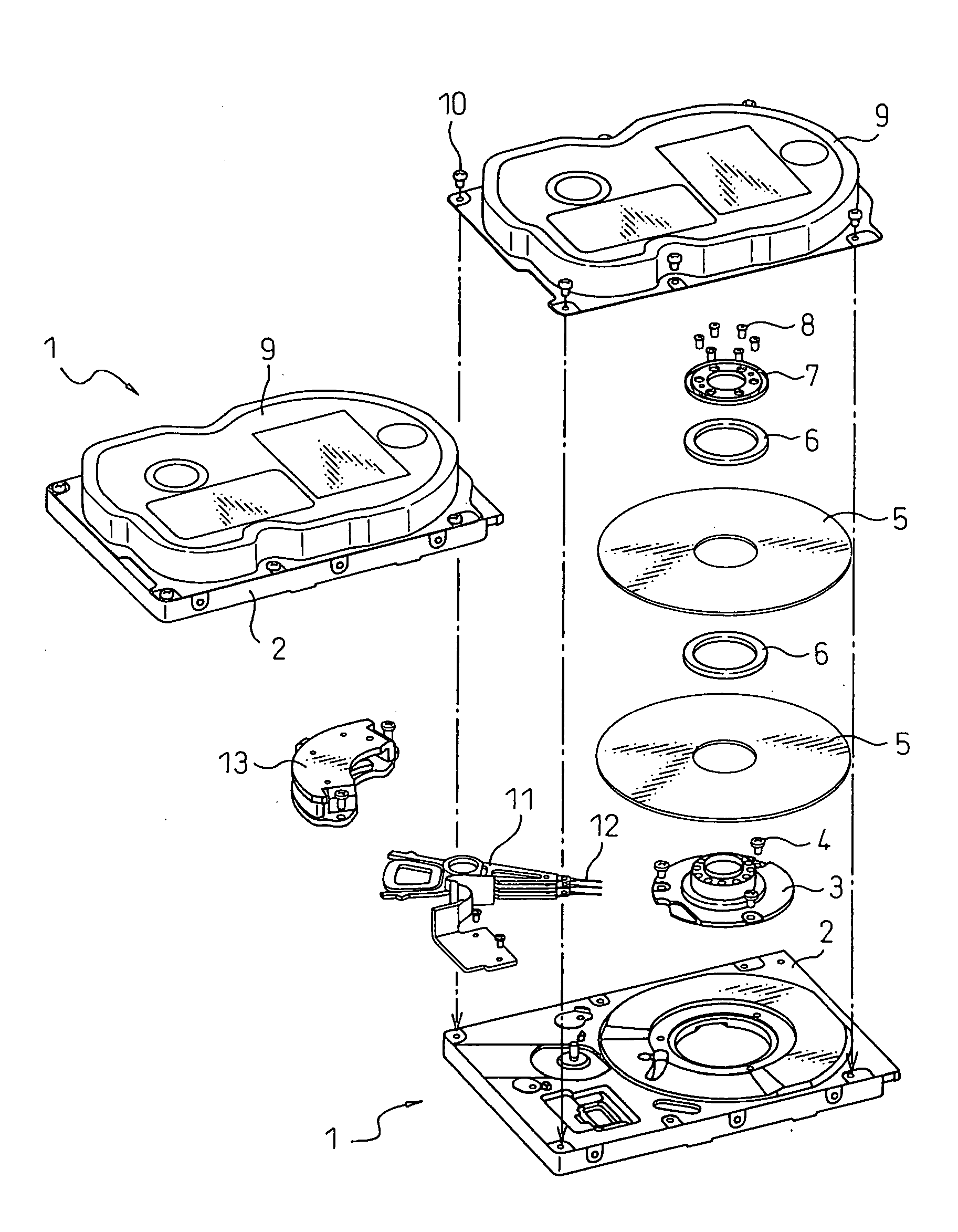
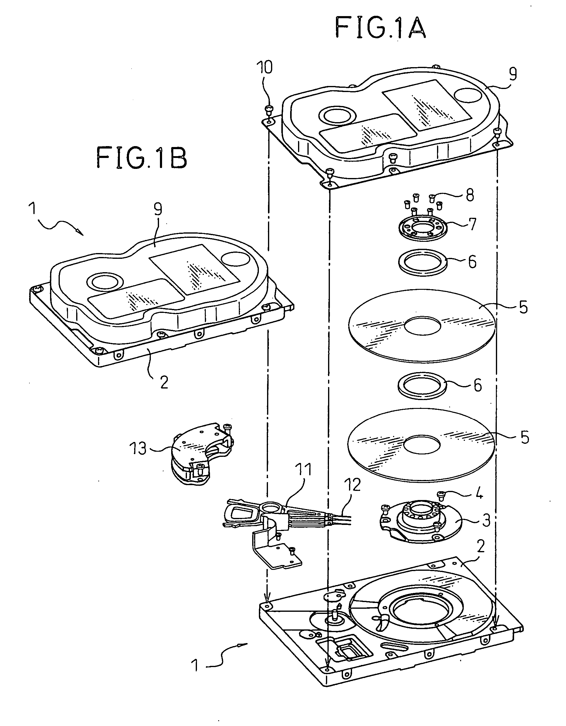
[0070] In order to erase the data from the magnetic disk device 1 by using the tray 21 the magnetic disk device 1 is accommodated in the disk device accommodation groove 63 of the tray 21, and a first demagnetizing operation is executed by inserting and extracting the tray 21 into and from the data erasing device 60A explained with reference to FIG. 3. Next, the magnetic disk device 1 is accommodated in the disk device accommodation groove 31 of the tray 21, and a second demagnetizing operation is executed by inserting and extracting the tray 21 into and from the data erasing device 60A explained with reference to FIG. 3.

[0071] According to the present invention, the demagnetizing operation in the direction parallel with the center line of the magnetic disk device 1 and the demagnetizing operation in the direction inclined from the center line of the magnetic disk device 1 are carried out, as explained above. Therefore, the magnet used in the data erasing device 60A shown in FIG. 3...

second embodiment

[0073] In order to erase the data from the magnetic disk device 1 by using the tray 22 the magnetic disk device 1 is accommodated into the disk device accommodation groove 32 of the tray 22, and a first demagnetizing operation is executed by inserting and extracting the tray 22 into and from the data erasing device 60A explained with reference to FIG. 3. Next, the magnetic disk device 1 is accommodated into the disk device accommodation groove 63A of the tray 22, and a second demagnetizing operation is executed by inserting and extracting the tray 22 into and from the data erasing device 60A explained with reference to FIG. 3.

[0074] When the tray 22 according to the second embodiment is used, the data erasing operation is carried out in two directions by inclining the direction of the tray 22 by 45 degrees from the center line of the magnetic disk device 1 to the left and to the right of the center line respectively. Therefore, the magnet used in the data erasing device 60A shown i...

third embodiment

[0076] In order to erase the data from the magnetic disk device 1 by using the tray 23 the magnetic disk device 1 is accommodated in the disk device accommodation groove 63 of the tray 23, and a first demagnetizing operation is executed by inserting and extracting the tray 21 into and from the data erasing device 60A explained with reference to FIG. 3. Next, the magnetic disk device 1 is accommodated in the disk device accommodation groove 33 of the tray 23, and a second demagnetizing operation is executed by inserting and extracting the tray 23 into and from the data erasing device 60A explained with reference to FIG. 3.

[0077] In the data erasing operation using the tray 23 according to the third embodiment, the data erasing operation in the direction parallel with the center line of the magnetic disk device 1 and the data erasing operation in the direction inclined from the center line of the magnetic disk device 1 are also carried out. Therefore, the magnet used in the data eras...


PUM

PropertyMeasurementUnit
angleaaaaaaaaaa
angleaaaaaaaaaa
magnetic fieldaaaaaaaaaa

Abstract

A data erasing device that erases data recorded on a magnetic disk, by a magnetic field generated in a horizontal direction by magnets, in order to prevent leakage of the data recorded on the magnetic disk of a magnetic disk device to be abandoned. The data erasing device includes a main body case having a path on which a tray is reciprocated, a demagnetizing circuit having plural permanent magnets adjacently disposed along the path in mutually adsorbing polarities, and a tray for accommodating the magnetic recording medium, and capable of reciprocating on the path. This tray includes a first accommodation groove and a second accommodation groove for accommodating the magnetic disk device. The first accommodation groove and the second accommodation groove cross each other to form an angle of 45 degrees or 90 degrees.

Description

CROSS-REFERENCE TO RELATED APPLICATION [0001] This application claims priority from, and incorporates by reference the entire disclosure of, Japanese Patent Application No. 2005-251850, filed on Aug. 31, 2005. BACKGROUND OF THE INVENTION [0002] 1. Field of the Invention [0003] The present invention relates to a data erasing device and, more particularly, to a data erasing device for a hard disk device used as a storage device in a computer. [0004] 2. Description of the Related Art [0005] Conventionally, in computers such as personal computers and the like, recording media for recording programs and data are necessary and, in recent years, hard disk devices using a disk coated with a magnetic material have become popular as such recording media. Such hard disk devices are built into the computer or are used as external hard disk devices connected to the computer via a cable, data being written into at least one internal disk via at least one head. The storage capacity of these types ...

Claims


Application Information

Patent Timeline
Patent Type & Authority Applications(United States)
IPC IPC(8): G11B5/03
CPCG11B5/024
Inventor KADOWAKI, YOSHINORISUZUKI, HISATOUEMATSU, HIROYUKIHASEGAWA, HIROSHI
Owner KK TOSHIBA
Why Eureka
Try Eureka