Graphical interconnection of hardware signals

a hardware signal and interconnection technology, applied in the field of graphical interconnection of hardware signals, can solve the problems of malfunctions of the controller system, user who does not know the convention, and is hardly in a position to plan an automation system project without assistance, and it is difficult to understand the different mappings

Active Publication Date: 2007-03-22
SIEMENS AG
View PDF3 Cites 4 Cited by
  • Summary
  • Abstract
  • Description
  • Claims
  • Application Information

AI Technical Summary

Benefits of technology

[0006] An object of the invention is to create a system of the type mentioned at the start with which the hardware signals of a device, especially of a controller device, can be logically linked in a simple manner graphically to program elements of a program environment. An object of the invention is also to develop a method with which a user can logically link hardware signals of a device, especially of a controller device, graphically to program elements in a simple manner, i.e. without having to know the address convention used in the system.

Problems solved by technology

With an incorrectly used address—with syntactical errors—the engineering system can indicate an error; with other input errors the result is malfunctions of the controller system.
The problem with this solution is that a user who does not know the convention is hardly in a position to plan an automation system project without assistance.
Furthermore those making the change find it difficult to understand how the different mappings (symbol→address→hardware signal) function.
This is a significant barrier to getting started with a system.

Method used


Image

  • Graphical interconnection of hardware signals
  • Graphical interconnection of hardware signals
  • Graphical interconnection of hardware signals

Examples


Embodiment Construction

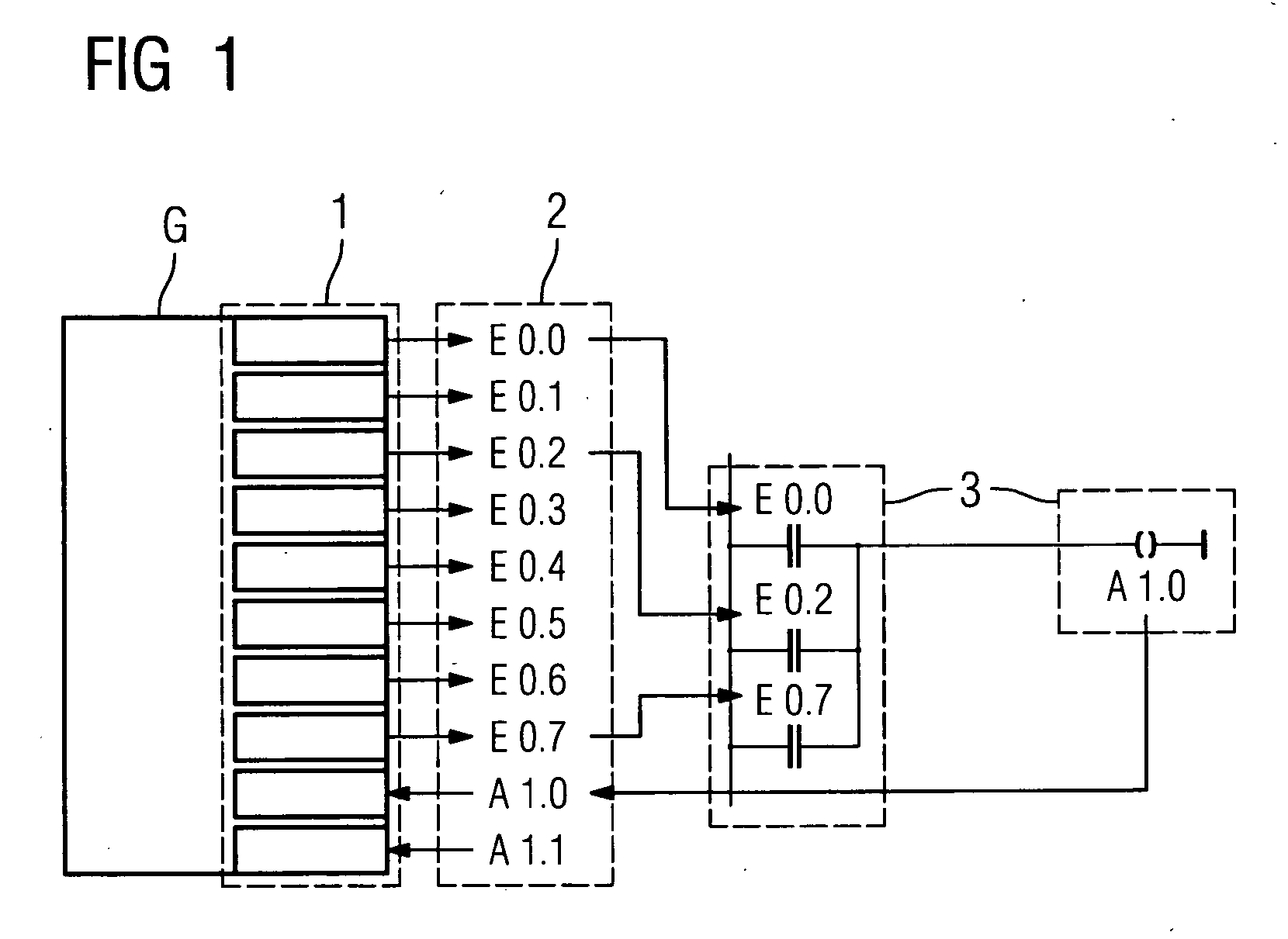
[0027]FIG. 1 shows the assignment of hardware signals of a device (G) to program elements 3 via logical addresses 2 according to the address convention of a PLC (Programmable Logic Controller). Each terminal 1 assigned to a hardware signal is assigned a logical address 2. These in their turn are assigned to program elements 3 for interconnection of the hardware signals.

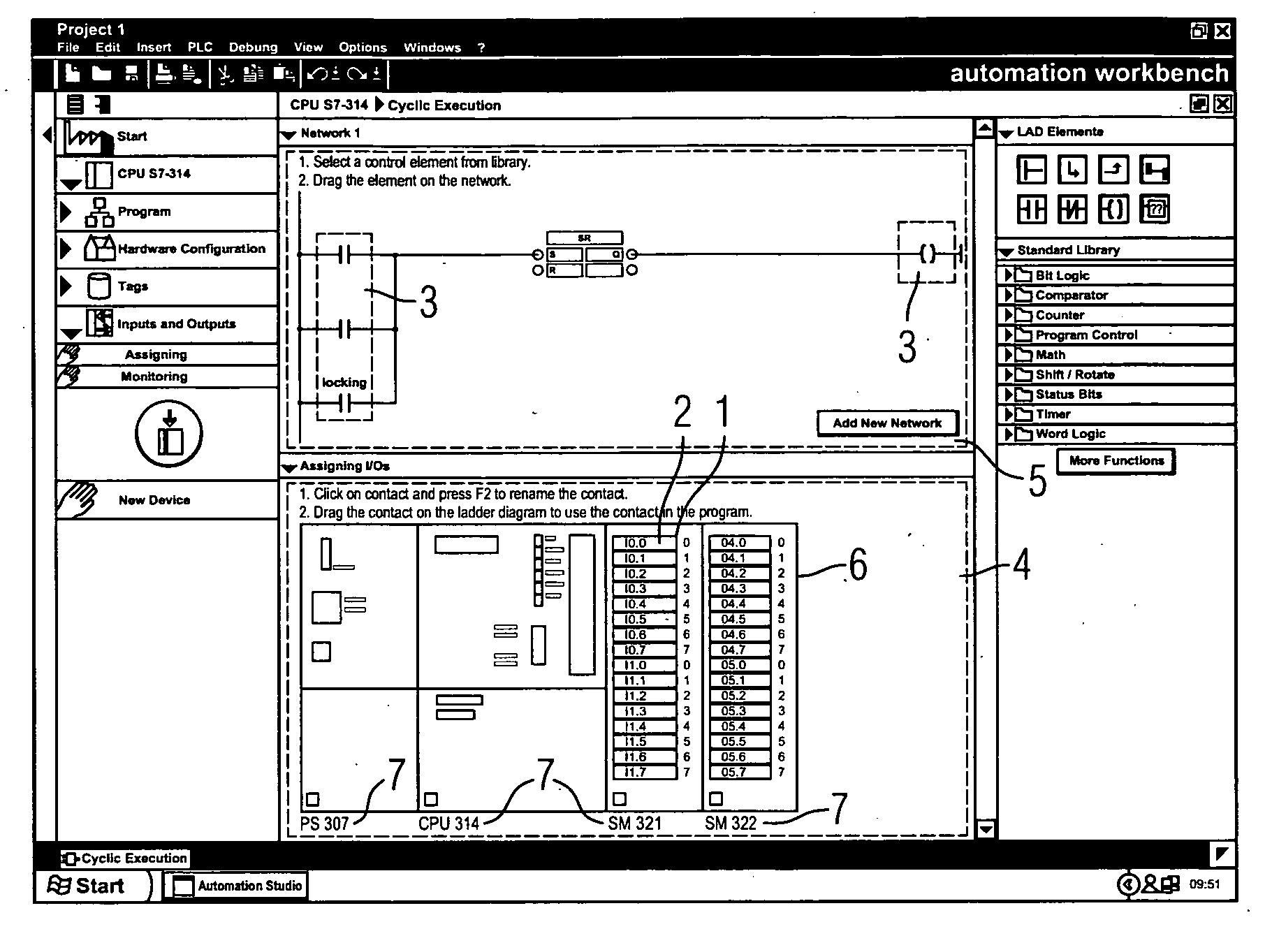
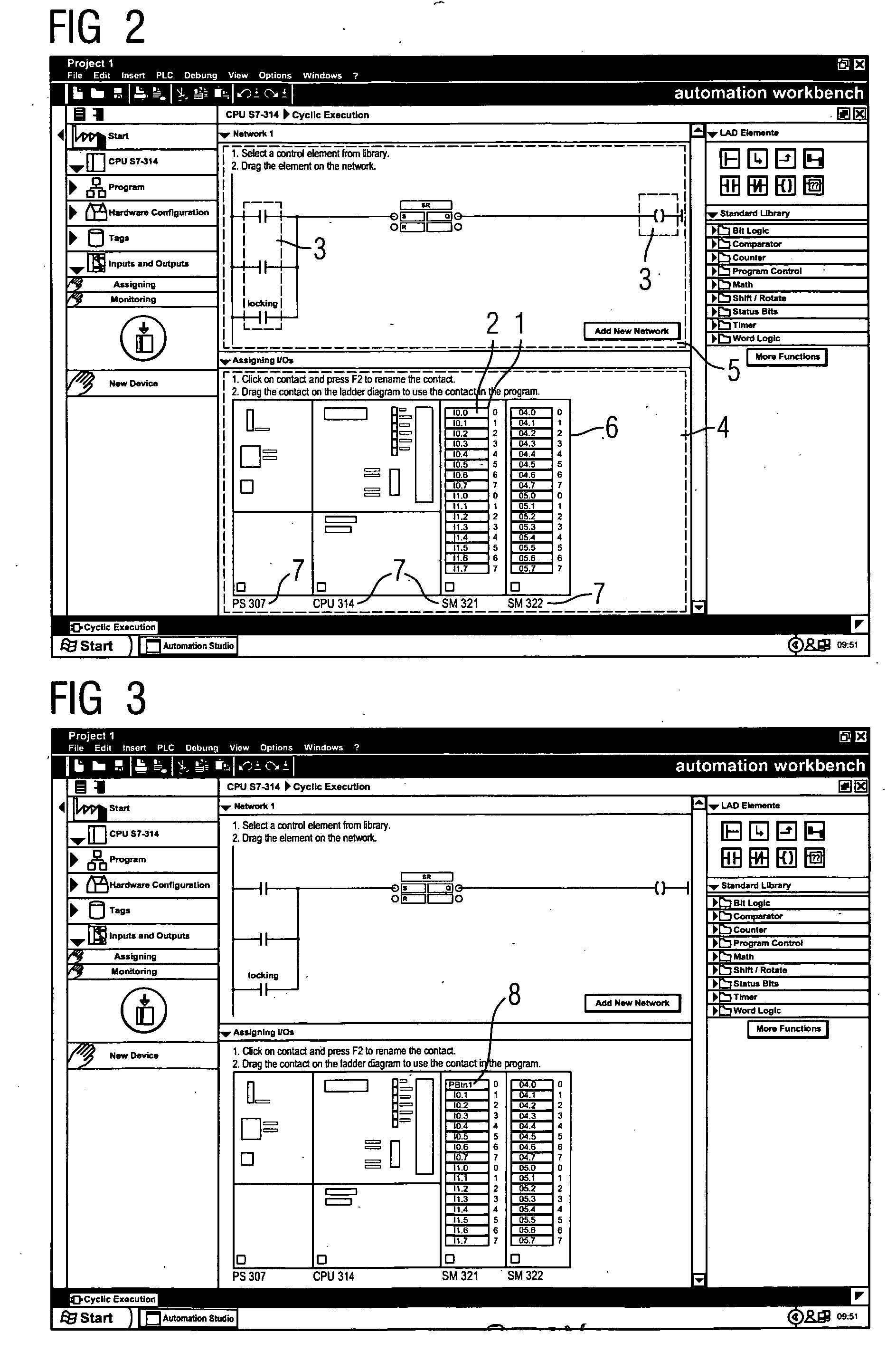
[0028]FIG. 2 shows a graphical user interface in accordance with the invention with a first subarea of the graphical user interface in which terminals 1 present on the device can be visualized in an at least schematic presentation 6, and a second subarea of the graphical user interface in which program elements 3 of a program environment, shown here by a contact plan, can be presented. All modules 7 and terminals 1 of the device are shown in the schematic presentation 6, and are shown in such a way that the user can recognize the real position of the terminals 1 again. This map 6 of the device is created by the syste...


PUM


Abstract

In one aspect, a system and a method for graphical interconnection of hardware signals of a device, especially of a controller device are provided. The object of the invention is to design the graphical interconnection in a simple manner so that a user can perform this function intuitively and without knowledge of the address convention used in the engineering system. This object is achieved by the inventive system and by the inventive method by the hardware signals being interconnected graphically with program elements of a programming environment using drag & drop. A clean copy of the Abstract that incorporates the above amendments is provided herewith on a separate page.

Description

CROSS REFERENCE TO RELATED APPLICATIONS [0001] This application claims priority of European application No. 05017627.0 EP filed Aug. 12, 2005, which is incorporated by reference herein in its entirety. FIELD OF INVENTION [0002] The invention relates to a system and a method for graphical interconnection of hardware signals of a device, especially of a controller device. BACKGROUND OF INVENTION [0003] This type of system is employed in particular in the area of industrial automation. A major task in the creation of an automation solution is the programming. This involves hardware signals of a controller system—that is input and output values of a controller device—technically being connected to a terminal and then logically linked in a meaningful manner in an engineering system to program elements, especially for programmable logic controllers (PLCs). To enable the desired hardware signal to be referenced it is necessary to enter an address which will be logically assigned to a hardw...

Claims


Application Information

Patent Timeline
Patent Type & Authority Applications(United States)
IPC IPC(8): G05B15/00
CPCG05B19/056G06F8/34G05B2219/13144G05B2219/13037Y02P90/02
Inventor MENZL, FRANZ-JOSEFMILDENBERGER, RALFIBARRA, PABLO MUNOZPLATZ, AXELSCHMIDT, JOHANNAWEHRFRITZ, WILHELMWEINLANDER, MARKUS
Owner SIEMENS AG
Why Eureka
Try Eureka