Fastener

a technology of fasteners and screws, applied in the direction of threaded fasteners, fastening means, screws, etc., can solve the problems of affecting the performance of the component, the bending or flexing of the fin, and the wobble of the hole of the tree-type fastener with the bent or flexed fin

Inactive Publication Date: 2007-06-14
ILLINOIS TOOL WORKS INC
View PDF33 Cites 34 Cited by
  • Summary
  • Abstract
  • Description
  • Claims
  • Application Information

AI Technical Summary

Benefits of technology

[0006] Features of embodiments of the invention include a low required insertion force combined with a high removal force and a robust, yet clean design. Because the fastener is fabricated as a single piece, the fastener may be manufactured with a relatively low tooling investment. Features of the invention may also be adapted with new or existing tree-type fastener designs such as 2-barb, 4-barb, and split tree, among other designs.

Problems solved by technology

When tree-type fasteners are subjected to excessive pull-out forces the fins have a tendency to bend or flex.
However, even if the fastener is prevented from being pulled out of the hole, the tree-type fastener with bent or flexed fins may now wobble in the hole due to the stack-up of the fins along the shaft.
If the fastener is for an automotive component, such as a routing clip, a fastener that may wobble in the hole could lead to undesirable performance of that component.
Even these designs, however, typically do not reach above 50-60 lbs. of removal force.

Method used


Image

  • Fastener
  • Fastener
  • Fastener

Examples


Embodiment Construction

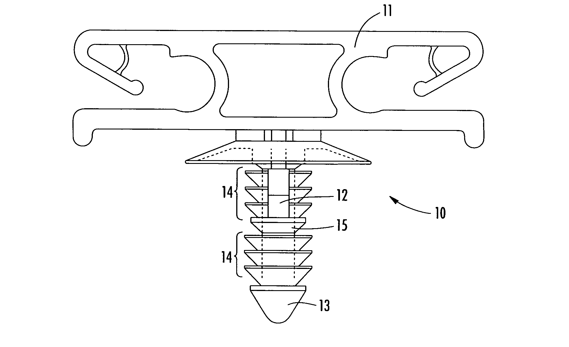
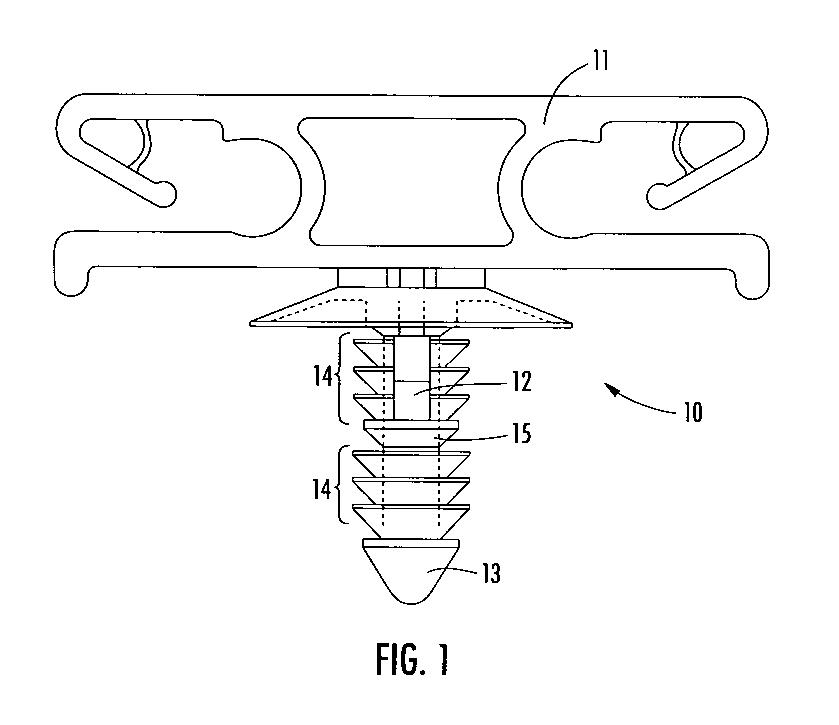
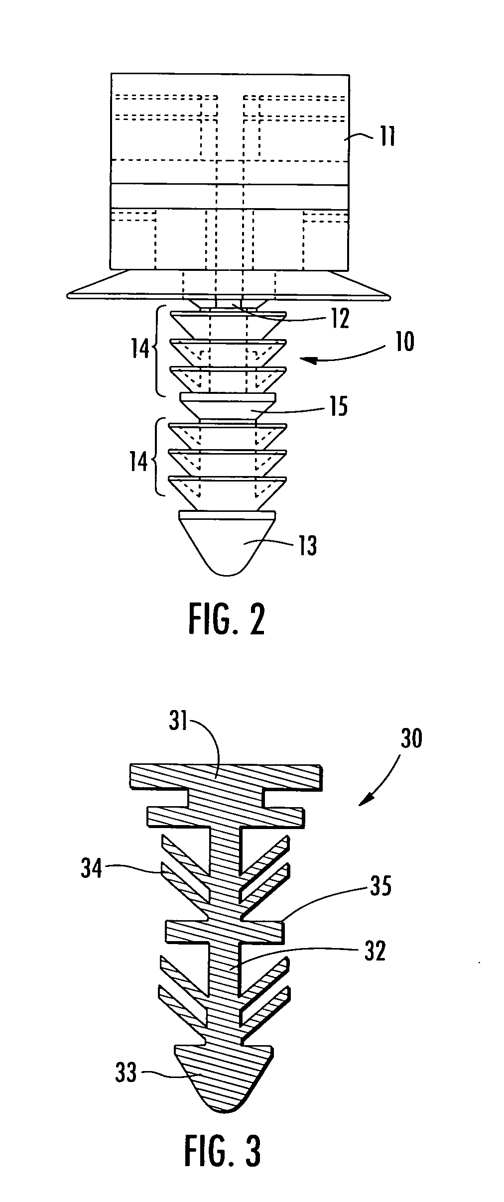
[0014] The Figures illustrate exemplary embodiments of tree-type fasteners of the invention. These embodiments may include a fin stabilization base, also referred to as a fin stabilizer or force multiplier base, located at one or more desired positions along the fastener shaft. In one embodiment, the fin stabilizer is located at a distance below the known work piece thickness of the application, as well as below any additional components attached to the work piece by the fastener. At this location, the fin stabilizer acts as a stop or support structure for the fins by supporting the underside of the fins to prevent the fins from rolling over or stacking-up one on top of another. By placing a fin stabilizer strategically along the shaft, the extraction force required to remove the fastener will significantly increase and wobbling due to damaged fins may also be prevented. It should be understood that additional fin stabilizers may be utilized to further increase the extraction force ...


PUM


Abstract

A tree-type fastener includes one or more fin stabilizer bases disposed on a shaft of the fastener. When the fastener is subjected to a pull-out force, the fins may be prevented from stacking up, buckling or bending by the fin stabilizer base. The stabilizer base is configured to provide no interference with a work piece when inserted in a work piece aperture. The fastener of the invention provides a high removal force to insertion force ratio and a strong, single piece device. The fastener may also be adapted for modification of new and existing tree-type fasteners.

Description

CROSS REFERENCE TO RELATED APPLICATIONS [0001] This Non-Provisional Application claims benefit to U.S. Provisional Application Ser. No. 60 / 750,105 filed Dec. 14, 2005.FIELD OF THE INVENTION [0002] The present invention relates generally to fasteners, and more particularly, to tree-type fasteners. BACKGROUND OF THE INVENTION [0003] It is known that tree-type fasteners are used to join component panels, one or more work pieces, or other structures. The tree-type fastener is typically made of a plastic material and includes multiple standard retention fins located along a longitudinal shaft, the fins extending outwardly from the shaft. The fins may have a shape such as annular, flat, angled, spiral or round, to name a few. These fasteners are designed to be driven axially into an aperture to connect one or more work pieces, and the fins may engage the edges of the aperture and the work piece surfaces to join together the work pieces. Known tree-type fasteners may be found, for example,...

Claims


Application Information

Patent Timeline
Patent Type & Authority Applications(United States)
IPC IPC(8): F16B19/00
CPCF16B21/084F16B21/086
Inventor SHEREYK, DAVID A.BENOIT, THOMAS A.
Owner ILLINOIS TOOL WORKS INC
Why Eureka
Try Eureka