
Faucet with constant temperature valve
a constant temperature valve and faucet technology, applied in the field of faucets, can solve the problems of improper temperature control response and inability to reduce the manufacture cost of high-precision products, and achieve the effect of reducing the manufacture cost and reducing the manufacture precision requiremen
- Summary
- Abstract
- Description
- Claims
- Application Information
AI Technical Summary
Benefits of technology
Problems solved by technology
Method used
Image

Examples
Embodiment Construction
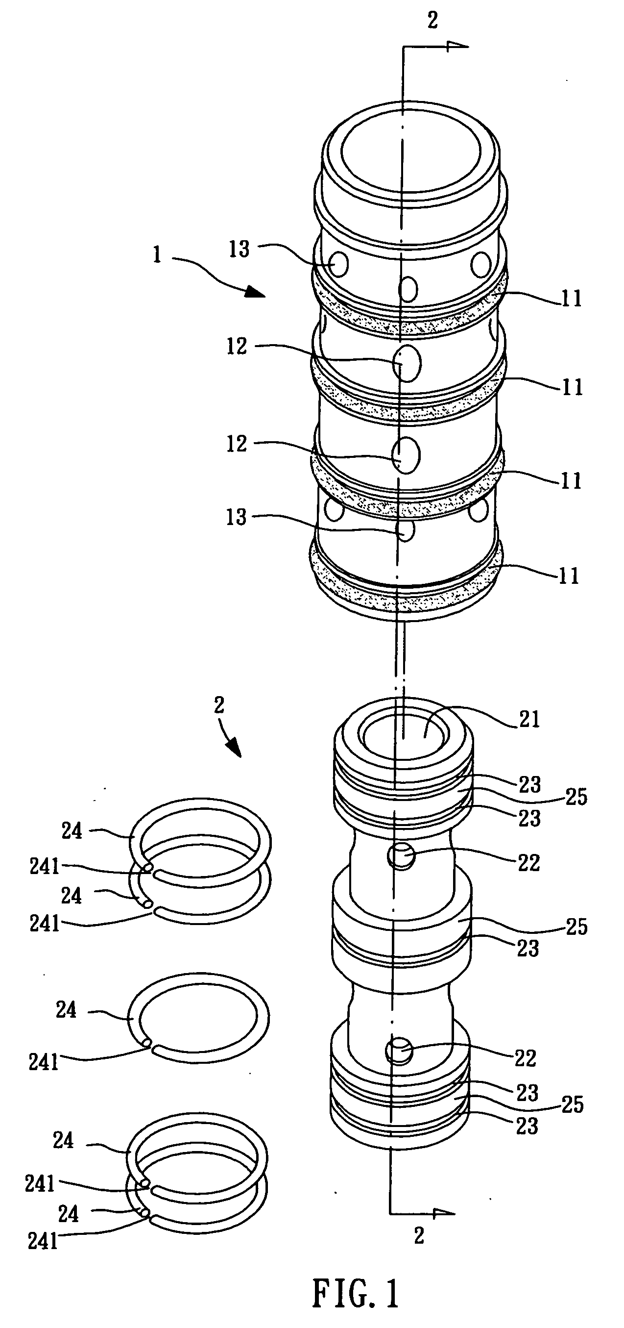
[0018] With reference to FIG. 1, a constant temperature valve in accordance with the present invention comprises a sleeve 1, an actuator 2 and a plurality of separate spring rings 24.
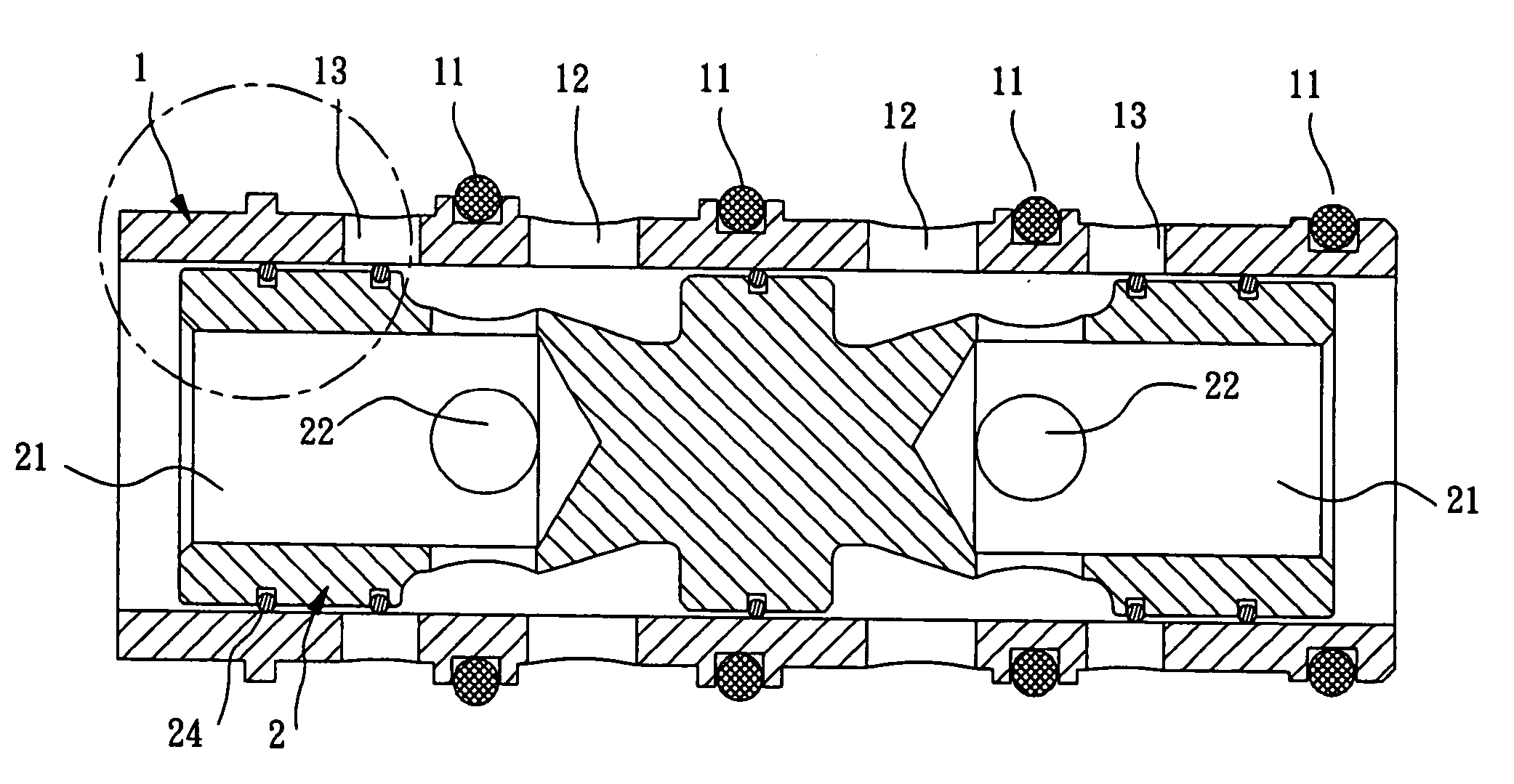
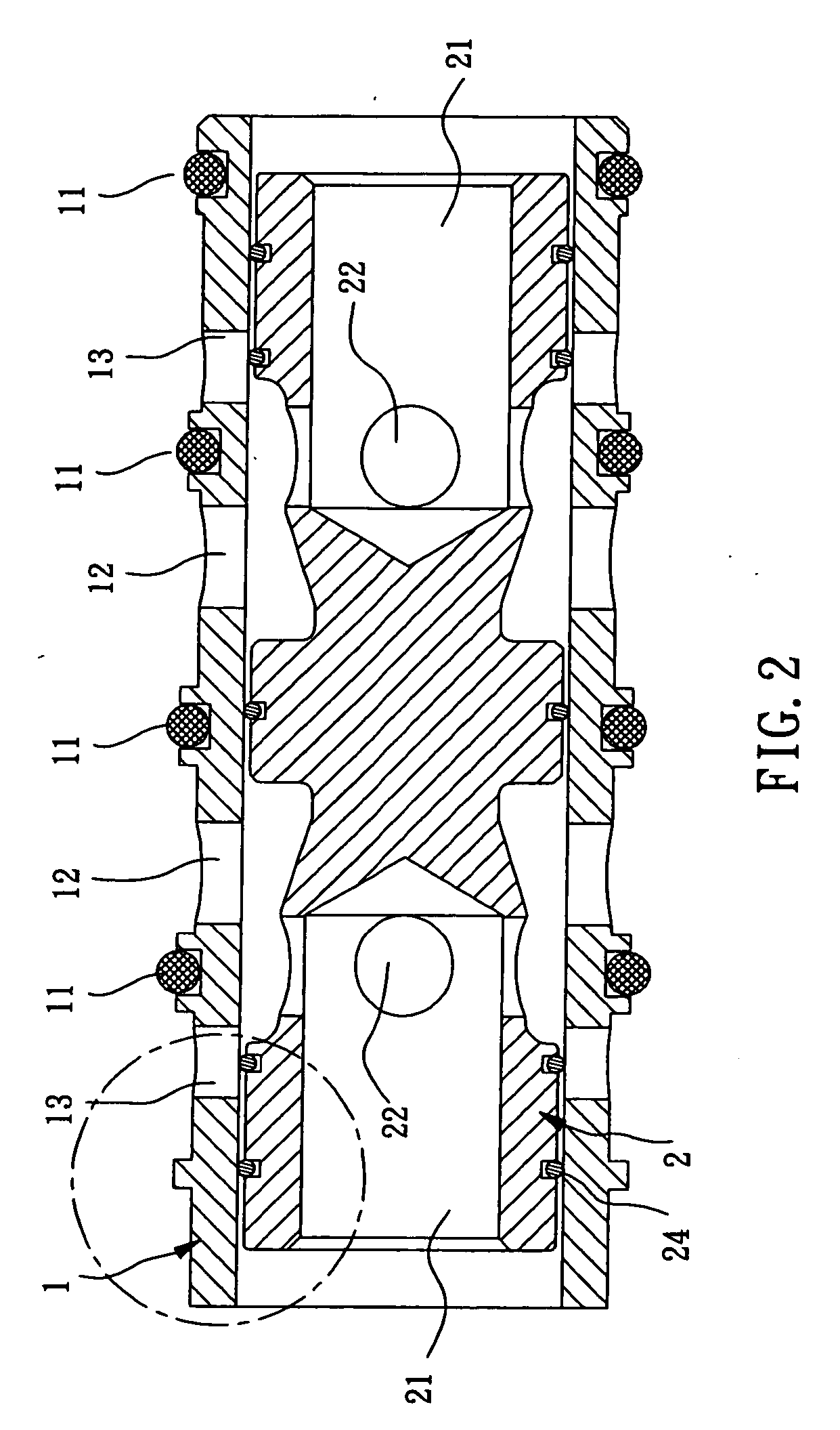
[0019] The sleeve 1 is cylindrical and hollow and is mounted on a faucet 4 in assembly. A plurality of O-shaped rubber rings 11 is mounted around the sleeve 1. The rubber rings 11 are distributed longitudinally on an outer peripheral of the sleeve 1 and divide the outer peripheral of the sleeve 1 into a plurality of sections. Each section defines a plurality of inlet holes 12 and outlet holes 13 for water inlet and outlet.
[0020] The actuator 2 is telescopically mounted in the sleeve 1 with interval therebetween. The actuator 2 forms a plurality of collars 25 on a peripheral thereof for fitting with sections of the sleeve 1. A pair of cavities 21 is respectively defined in opposite ends of the actuator 2 for providing water pressure to pull the actuator 2. A plurality of through holes 22 is defined in ...
PUM
 Abstract
Description
Claims
Application Information