Method for manufacturing laminate, and method for manufacturing ink jet-head

a manufacturing method and technology for ink jets, applied in piezoelectric/electrostrictive transducers, manufacturing tools, non-electric welding apparatuses, etc., can solve the problems of unwanted bonding between metal plates, low manufacturing efficiency and achieve low manufacturing efficiency, mass produced, and high manufacturing cost

Inactive Publication Date: 2006-03-30
BROTHER KOGYO KK
View PDF6 Cites 14 Cited by
  • Summary
  • Abstract
  • Description
  • Claims
  • Application Information

AI Technical Summary

Benefits of technology

[0005] A manufacturer of ink-jet heads must be able to manufacture many (mass produce) laminates by diffusion bonding metal plate sets including a plurality of metal plates. In such situations, manufacturing efficiency is low and manufacturing cost is high if the laminates are manufactured one by one by subjecting metal plate sets to diffusion bonding one set at a time. Consequently, there is a need for a technique with which metal plate sets can be mass produced with diffusion bonding more efficiently.

Problems solved by technology

In such situations, manufacturing efficiency is low and manufacturing cost is high if the laminates are manufactured one by one by subjecting metal plate sets to diffusion bonding one set at a time.
When a plurality of metal plate sets are stacked together and directly subjected to diffusion bonding in an effort to manufacture a plurality of laminates at the same time, unwanted bonding ends up occurring between the two metal plates respectively belonging to different metal plate sets as well.
In this case, the plates for preventing diffusion bonding have to be readied separately, and an extra step is needed for these plates to be interposed between the plurality of metal plate sets, which results in increasing the manufacturing cost.
Accordingly, a plurality of laminates can be manufactured at once, which shortens the manufacturing process.

Method used


Image

  • Method for manufacturing laminate, and method for manufacturing ink jet-head
  • Method for manufacturing laminate, and method for manufacturing ink jet-head
  • Method for manufacturing laminate, and method for manufacturing ink jet-head

Examples


first embodiment

[0048] A first embodiment of the present invention will be described. This first embodiment is an example of applying the present invention to the manufacture of an ink-jet head that discharges ink.

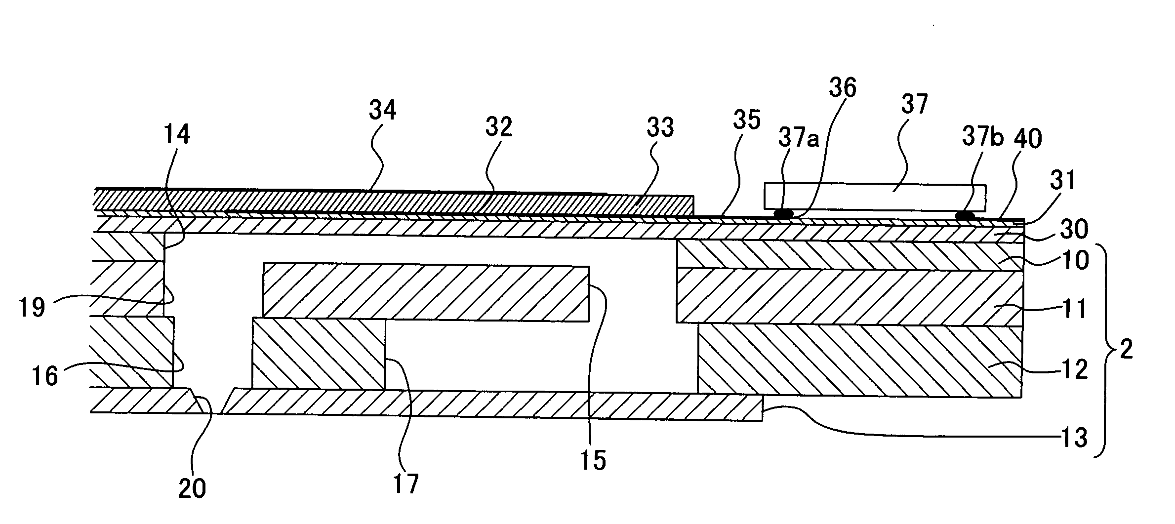
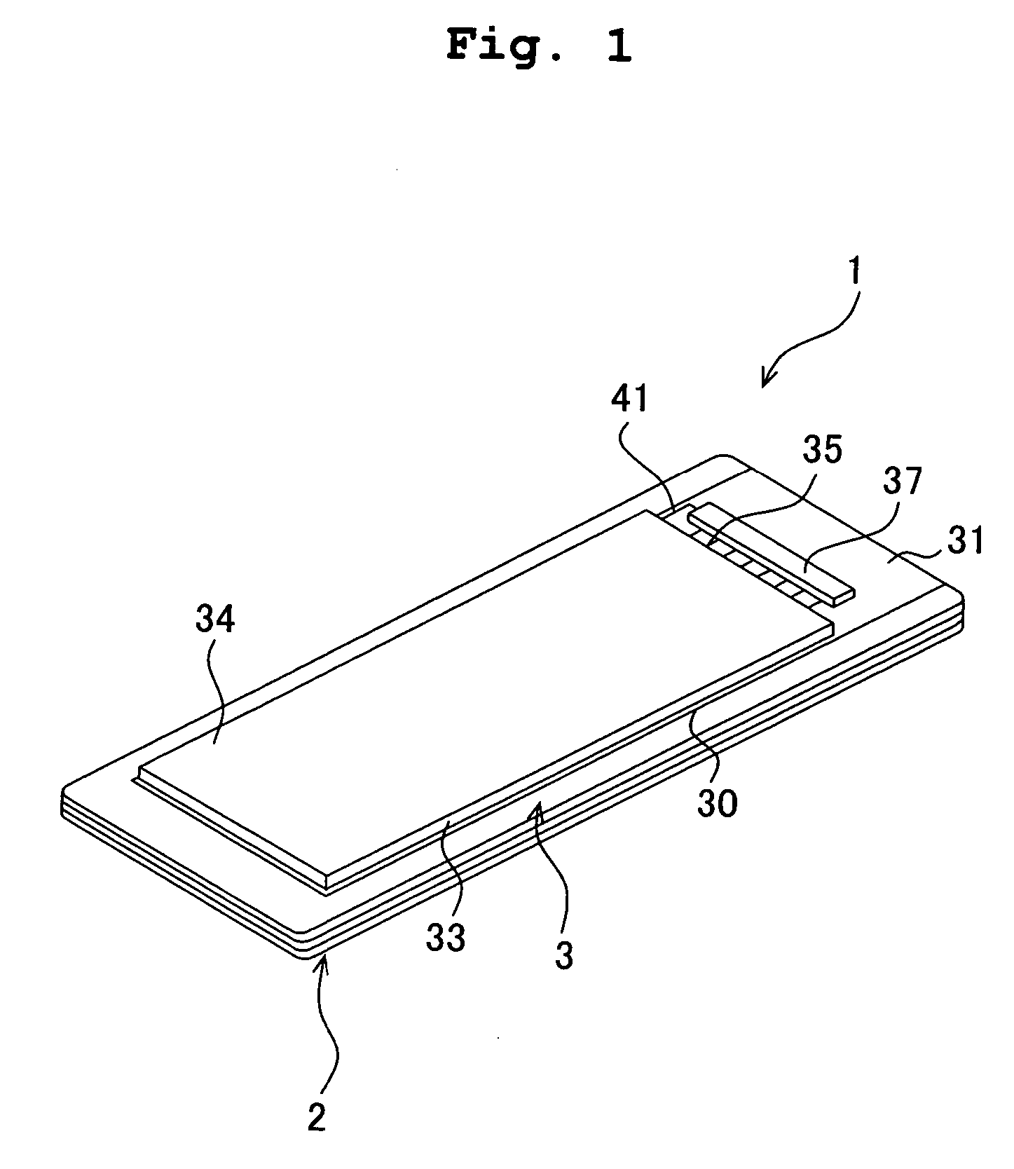
[0049] First, an ink-jet head 1 will be described through reference to FIGS. 1 to 4. The vertical direction in this description is defined as the vertical direction in the sheet surface of FIG. 1. As shown in FIG. 1, the ink-jet head 1 includes a channel unit 2 which is rectangular in plan view and has an ink channel formed in its interior, and a piezoelectric actuator 3 which is stacked on the top surface of this channel unit 2.

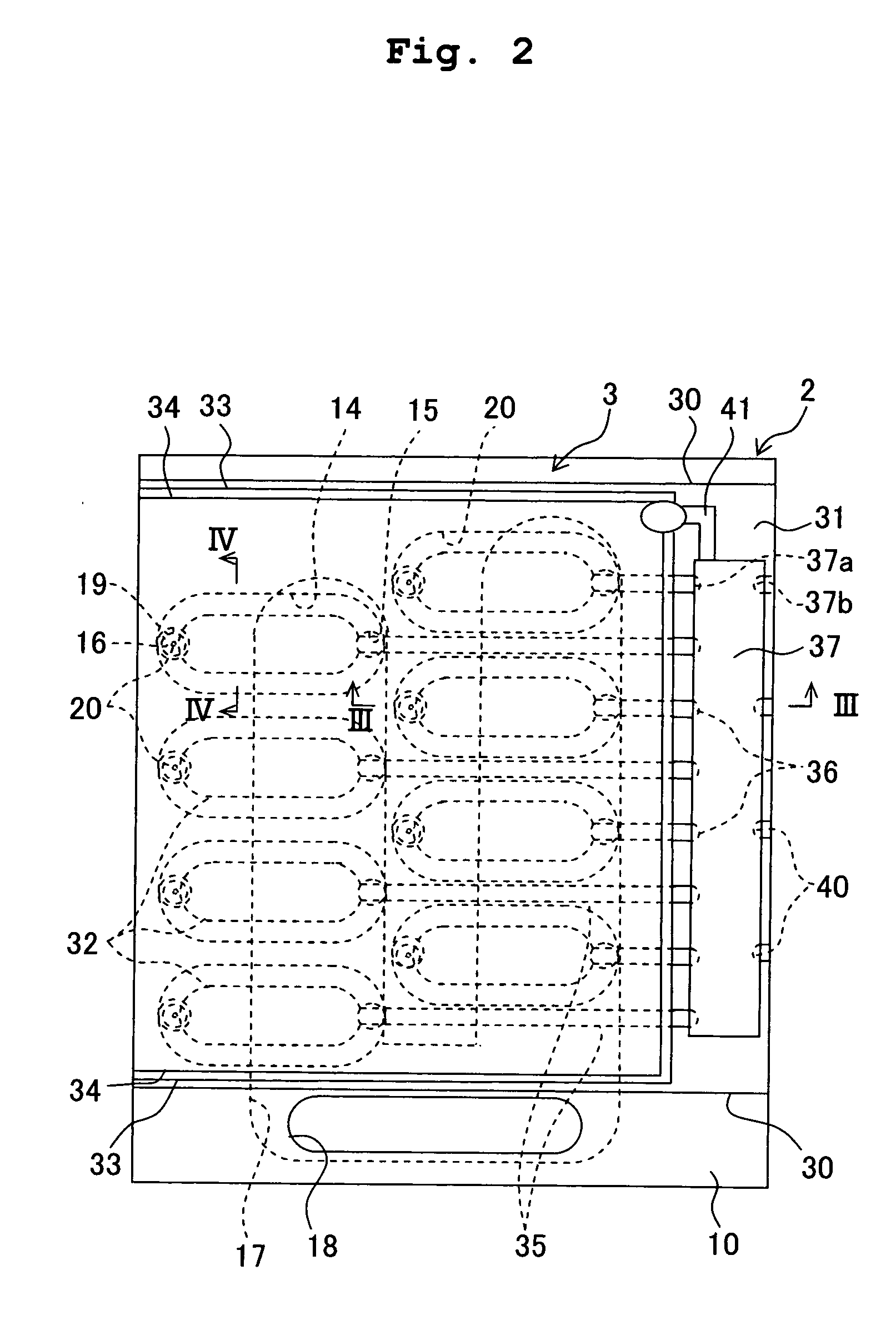
[0050] As shown in FIGS. 2 to 4, the channel unit 2 includes a cavity plate 10, a base plate 11, a manifold plate 12, and a nozzle plate 13, and these four plates 10 to 13 are bonded in a stacked state. Of these, the cavity plate 10, the base plate 11, and the manifold plate 12 are substantially rectangular plates made of metal (such as stainless steel), and the...

second embodiment

[0071] Next, a second embodiment of the present invention will be described through reference to FIGS. 19 to 21. In this embodiment, a metal nozzle plate 13a is provided to the lower surface of the manifold plate 12, a water repellent ceramic layer 13b is formed as an insulating ceramic layer on one side thereof, and plate sets are stacked via the water repellent ceramic layer 13b and diffusion-bonded.

[0072] As shown in FIG. 19, the water repellent ceramic layer 13b, which is made of water repellent zirconia, is formed by aerosol deposition on the lower surface (the side from which ink is ejected through the nozzles) of the metal nozzle plate 13a, in which nozzles 20 as through-holes have been formed (insulating ceramic layer formation step). Next, as shown in FIG. 20, a plate set 50a is formed by stacking five metal plates including the vibration plate 30, the cavity plate 10, the base plate 11, the manifold plate 12, and the nozzle plate 13a having the water repellent ceramic lay...

third embodiment

[0077] A third embodiment of the present invention will be described through reference to FIGS. 22A to 22C. In this embodiment, an ink-jet head is manufactured in the same manner as in the second embodiment, except that the piezoelectric layer is formed directly over the vibration plate, without any insulating ceramic layer being interposed.

[0078] Everything up to the bonding step shown in FIG. 20 is performed just as in the second embodiment, after which, as shown in FIG. 22A, a layer 33a of a piezoelectric ceramic (piezoelectric layer) whose main component is lead zirconate titanate (PZT) is formed on the top surface of the vibration plate 30 by aerosol deposition (AD), sol-gel method, or sputtering. Next, a heat treatment is performed at about 600° C. to promote the crystal growth of the PZT texture of the piezoelectric layer 33a. After this, individual electrodes 32a are formed by printing on the surface of the piezoelectric layer 33a shown in FIG. 22B (individual electrode for...


PUM

PropertyMeasurementUnit
thermal conductivityaaaaaaaaaa
volumeaaaaaaaaaa
piezoelectricaaaaaaaaaa

Abstract

A method for manufacturing an ink-jet head includes the steps of: forming an insulating ceramic layer on one surface of a vibration plate; stacking a plurality of plate sets each having a plurality of metal plates which forms a channel unit, the other surface of the vibration plate being disposed on a cavity plate which is included in the plurality of metal plates and which forms a pressure chamber, the plate sets being stacked via the insulating ceramic layer; and heating the plurality of stacked plate sets so that the metal plates and the vibration plate of each of the plate sets are simultaneously bonded by diffusion bonding. As a result, a plurality of laminates can be manufactured at once by diffusion bonding the metal plates of the plurality of metal plate sets all together, without any diffusion bonding between two metal plates respectively belonging to different metal plate sets.

Description

BACKGROUND OF THE INVENTION [0001] 1. Field of the Invention [0002] The present invention relates to a method for manufacturing a laminate by diffusion bonding a plurality of stacked metal plates, and to a method for manufacturing an ink-jet head. [0003] 2. Description of the Related Art [0004] Metal diffusion bonding (hereinafter referred to as diffusion bonding), in which a plurality of stacked metal plates are joined by heating these metal plates under pressure, is generally used in many different fields. For example, U.S. Patent Application Publication NO. U.S. 2004 / 0080585A1 (corresponding to Japanese Patent Application Laid-open No. 2004-136462, FIGS. 1 to 5) discloses that a channel unit of an ink-jet head having an ink channel in its interior is manufactured by bonding a plurality of stacked plates by diffusion bonding. SUMMARY OF THE INVENTION [0005] A manufacturer of ink-jet heads must be able to manufacture many (mass produce) laminates by diffusion bonding metal plate se...

Claims


Application Information

Patent Timeline
Patent Type & Authority Applications(United States)
IPC IPC(8): B23K20/00H01L21/30H01S4/00
CPCB23K20/023B41J2/161B41J2/1623B41J2/1626B41J2/1642Y10T156/1056B41J2/1646B41J2002/14491Y10T29/49002Y10T29/42Y10T29/49401B41J2/1643H01L2224/16225
Inventor KOBAYASHI, KAZUO
Owner BROTHER KOGYO KK
Why Eureka
Try Eureka