Inorganic, Dielectric, Grid Polarizer and Non-Zero Order Diffraction Grating

a grid polarizer and dielectric technology, applied in the field of dielectrics, grid polarizers and non-zero order diffraction gratings, can solve the problems of unwanted astigmatism, take up valuable space, ghost images, etc., and achieve the effect of reducing ghost images, reducing back reflection, and conserving space in optical design

Inactive Publication Date: 2007-07-19
MOXTEK INC
View PDF99 Cites 20 Cited by
  • Summary
  • Abstract
  • Description
  • Claims
  • Application Information

AI Technical Summary

Benefits of technology

[0013] It has been recognized that it would be advantageous to develop a polarizer device capable of reducing back reflection, and thus capable of reducing ghost images when used in an imaging system or display system. In addition, it has been recognized that it would be advantageous to develop a polarizer device capable of polarizing and further controlling the light, such as the direction or modes of reflection. In addition, it has been recognized that it would be advantageous to develop a non-zero order type polarizer device capable of polarizing light while reflecting only light of non-zero order, and without reflecting light of the zero order. Furthermore, it has been recognized that it would be advantageous to develop an imaging system with such a wire grid polarizer or polarizer device capable of conserving space in the optical design, and capable reducing ghost images and unwanted astigmatism. It has been recognized that it would be advantageous to develop a polarizer or polarizing beam splitter that has high contrast in reflection and / or transmission, can withstand high temperatures and / or high energy flux, and that is simpler to manufacture. In addition, it has been recognized that it would be advantageous to develop a polarizer that is inorganic and dielectric.

Problems solved by technology

Such polarizers, however, can also back reflect a portion of the incident light resulting in a ghost image.
Tilting the polarizer, however, can take-up valuable space in a compact design, and can cause unwanted astigmatism.
Such MacNeille PBSs generate no astigmatism, but have a narrow acceptance angle, and have significant cost and weight.
In addition, polymer materials are organic and not as capable of withstanding higher temperatures or higher energy flux.
Such polarizers, however, still have conductive materials.

Method used


Image

  • Inorganic, Dielectric, Grid Polarizer and Non-Zero Order Diffraction Grating
  • Inorganic, Dielectric, Grid Polarizer and Non-Zero Order Diffraction Grating
  • Inorganic, Dielectric, Grid Polarizer and Non-Zero Order Diffraction Grating

Examples


Embodiment Construction

)

[0034] Definitions

[0035] The terms polarizer and polarizing beam splitter are used interchangeably herein. Both are referred to herein as polarizers or polarizer devices.

[0036] The term dielectric is used herein to mean non-metallic.

[0037] The term continuous is used here to denote continuous in at least two dimensions, such as continuous in a plane or continuous across a planar surface in both directions.

[0038] Description

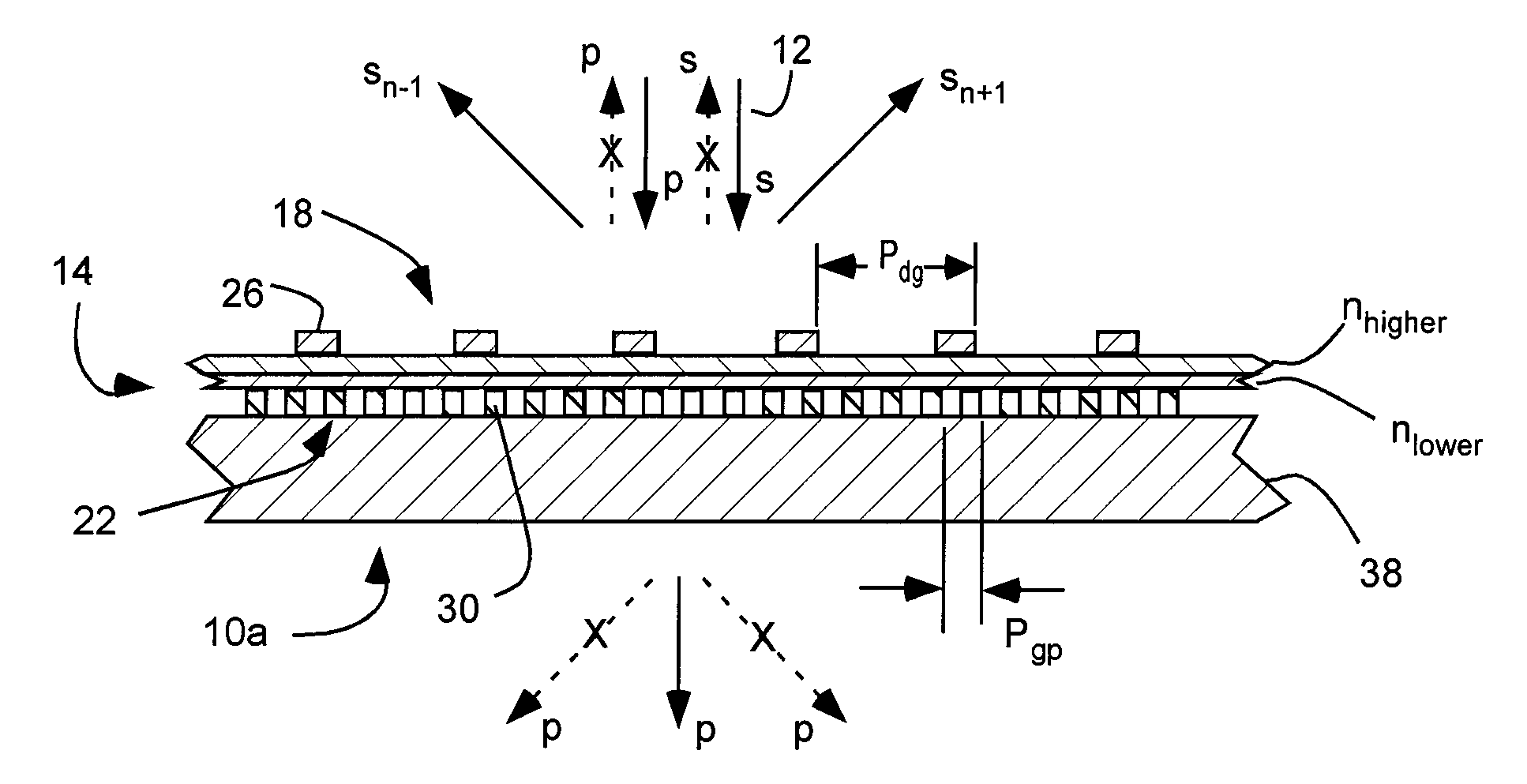
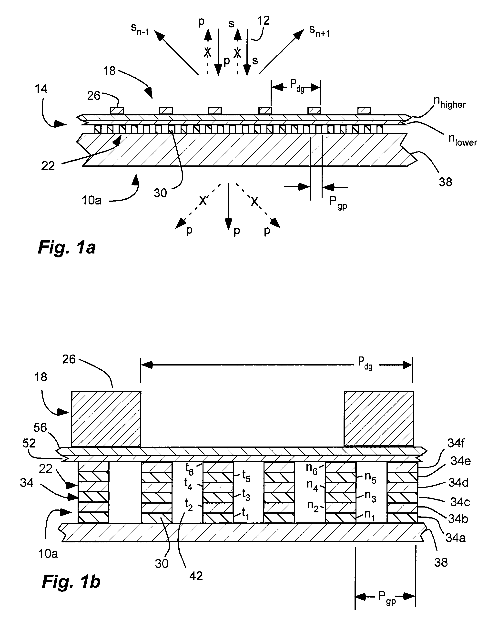
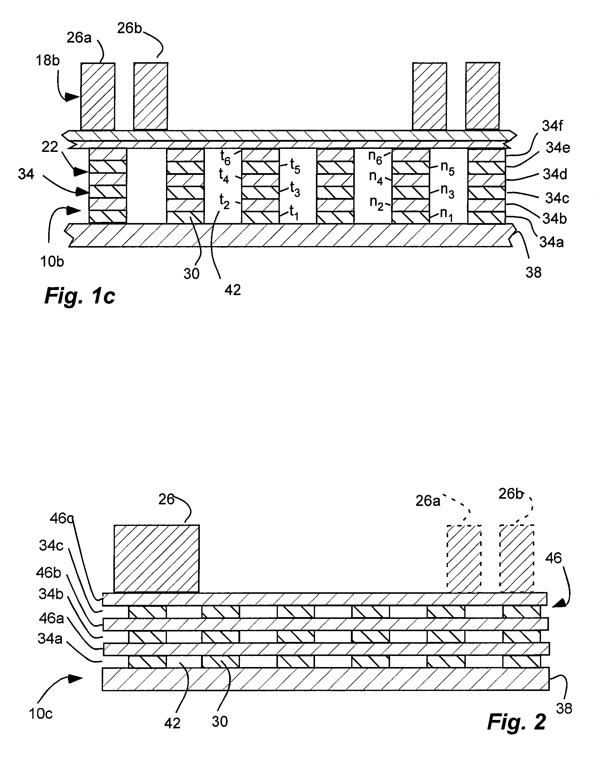
[0039] As illustrated in FIGS. 1a-2, polarizer devices in exemplary implementations of the invention are shown which can be used to polarize and further control light, and which can be used with image or display systems. Such polarizer devices can polarize and further control light, such as by reducing zero order reflections, or back reflection. Such polarizer devices can be a combination of an inorganic, dielectric grid polarizer and a diffraction grating, configured to reduce zero order back reflections of s-polarized light. It will be appreciated that oth...


PUM


Abstract

An inorganic, dielectric grid polarizer includes an optical stack with a diffraction grating and an inorganic, dielectric grid polarizer. The inorganic, dielectric grid polarizer includes a stack of film layers with an array of parallel ribs in accordance with PGP<λ / 2 where PGP is the period of the ribs and λ is the wavelength of the light. The diffraction grating includes an array of elongated parallel dielectric ribs in accordance with PDG>λ / 2 where PDG is the period of the ribs.

Description

RELATED APPLICATIONS & PRIORITY CLAIM [0001] This is a continuation-in-part of U.S. patent application Ser. No. 11 / 640,112 filed Dec. 15, 2006, which is a continuation-in-part of U.S. patent application Ser. No. 11 / 005,927 filed Dec. 6, 2004, which is herein incorporated by reference. [0002] This is a continuation-in-part of U.S. patent application Ser. Nos. 11 / 469,210; 11 / 469,226; 11 / 469,241; 11 / 469,253 and 11 / 469,266, filed Aug. 31, 2006; which are herein incorporated by reference. [0003] This is related to U.S. patent application Ser. Nos. 11 / 475,857 and 11 / 478,459, filed Jun. 26, 2006; which are herein incorporated by reference.BACKGROUND [0004] 1. Field of the Invention [0005] The present invention relates generally to a combined inorganic, dielectric grid polarizer and diffraction grating to polarize and further control light, such as by reducing zero order back reflection. [0006] 2. Related Art [0007] Diffraction gratings are a periodic structure of dielectric material with a...

Claims


Application Information

Patent Timeline
Patent Type & Authority Applications(United States)
IPC IPC(8): G02B5/30
CPCG02B5/3058
Inventor PERKINS, RAYMOND T.
Owner MOXTEK INC
Why Eureka
Try Eureka