Operation apparatus

Inactive Publication Date: 2007-07-26
DENSO CORP
View PDF15 Cites 9 Cited by
  • Summary
  • Abstract
  • Description
  • Claims
  • Application Information

AI Technical Summary

Benefits of technology

[0007]It is an object of the present invention to provide an operation apparatus to allow the number of detecting units to be smaller than the number of detected tilt directions. Further, this operatio

Problems solved by technology

This causes disadvantage that a large number of detectors are required although the number of tilt directions is relatively l

Method used


Image

  • Operation apparatus
  • Operation apparatus
  • Operation apparatus

Examples


Embodiment Construction

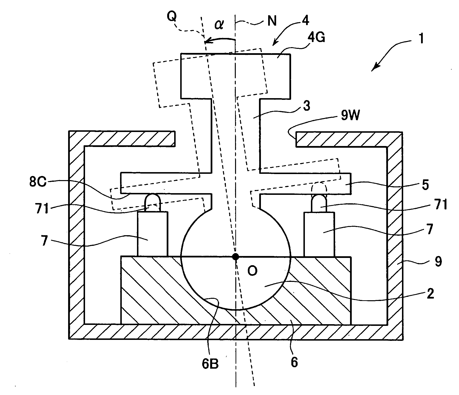
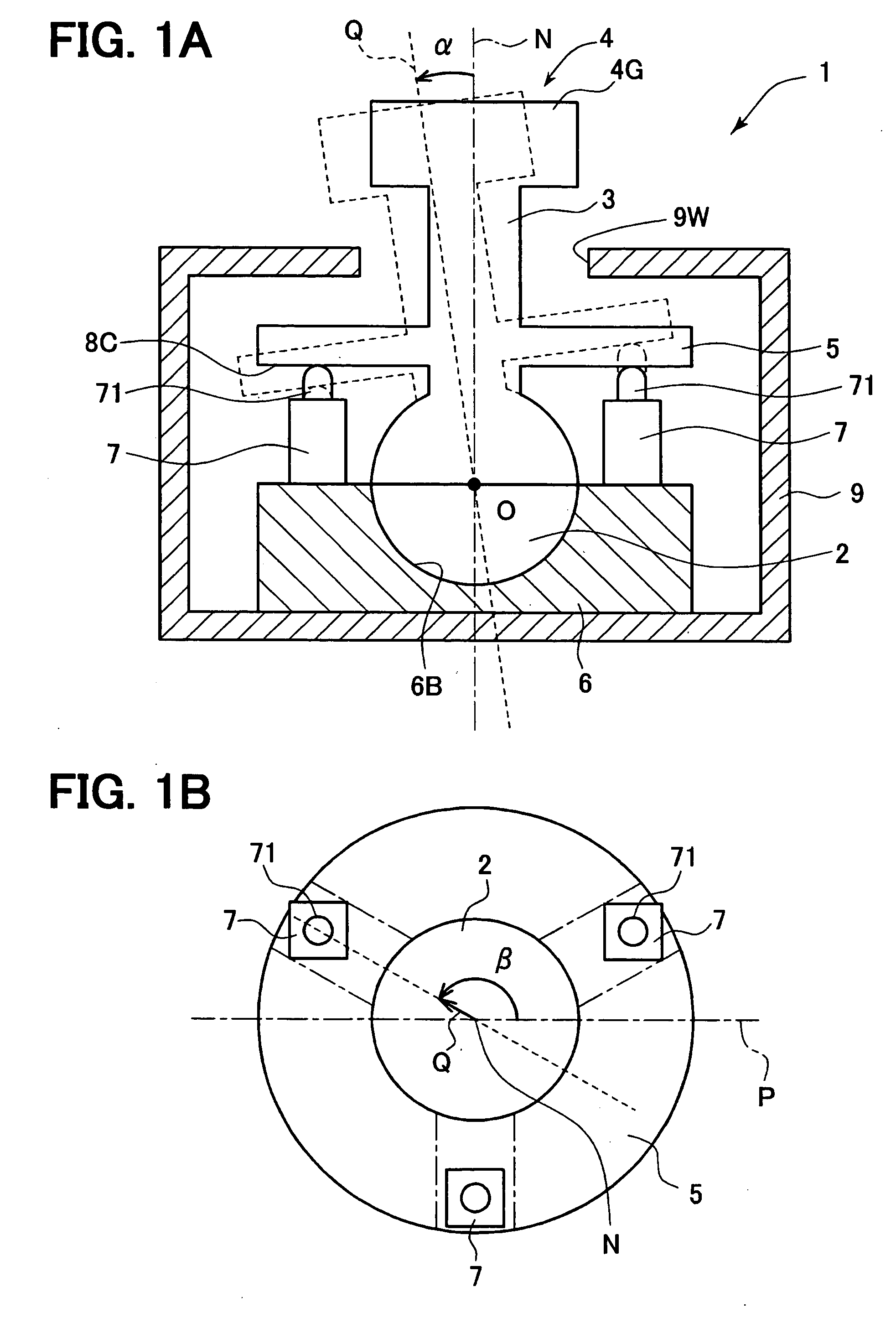
[0027]An operation apparatus as an embodiment according to the present invention will be explained below. As shown in FIG. 1, an operation apparatus 1 includes (i) an operation unit 4 for a user to hold and tilt for performing a tilt operation and (ii) a reception unit 6 to receive and support the operation unit 4. Here, as a force is applied to tilt the operation unit 4, the reception unit 6 allows a basic axis Q of the operation unit 4 to tilt against a neutral axis N towards one of mutually different more than three radial directions with a tilt center O located on the basic axis Q functioning as a supporting point. In this embodiment, multiple radial directions can be uninterruptedly detected within 360 degrees around the neutral axis N.

[0028]The operation unit 4 includes a detection subject member (or detectable member) 5, which tilts integrally with the operation unit 4. The detection subject member 5 is shaped of a disc to outwardly protrude from the circumferential surface o...


PUM


Abstract

An operation unit is used for a user to perform a tilt operation. The operation unit includes a disc-shaped detection subject member with a detection subject plane, which intersects with a basic axis Q of the operation unit and is movable integrally with the operation unit. Three detecting units are fixed in three different disposed positions surrounding a neutral axis N to detect displacement parallel with the neutral axis, which is generated by movement of the detection subject plane. A computing unit determines three-dimensional detected positions M1, M2, M3 of the detection subject plane by using (i) the disposed positions (X, Y) of the three detecting units and (ii) displacement detection outputs Z detected by the three detecting units. A tilt direction, in which the operation unit is tilted, is determined using a displacement plane DP defined by the three-dimensional detected positions M1, M2, M3.

Description

CROSS REFERENCE TO RELATED APPLICATION[0001]This application is based on and incorporates herein by reference Japanese Patent Application No. 2006-17102 filed on Jan. 26, 2006.FIELD OF THE INVENTION[0002]The present invention relates to an operation apparatus used for operating an electronic apparatus.BACKGROUND OF THE INVENTION[0003]Patent documents 1 and 2 propose operation apparatuses using tilt operations for input to electronic apparatuses. For instance, a tilt operation is performed in a predetermined direction with a predetermined tilt center functioning as a supporting point. Of this tilt operation, displacement in the predetermined direction is detected, as an input, by a detector such as a sensor or switch.[0004]In these operation apparatuses, one detector is assigned to one tilt direction; in specific, each of four detectors is provided to detect one of four tilt directions. This causes disadvantage that a large number of detectors are required although the number of tilt...

Claims


Application Information

Patent Timeline
IPC IPC(8): H01H19/00G06F3/0338
CPCG05G1/02G05G2009/04711G05G2009/04707G05G9/047
Inventor ITO, MASAHIRO
Owner DENSO CORP
Why Eureka
Try Eureka