

Fuel cell system
- Summary
- Abstract
- Description
- Claims
- Application Information
AI Technical Summary
Benefits of technology
Problems solved by technology
Method used
Image

Examples
first embodiment
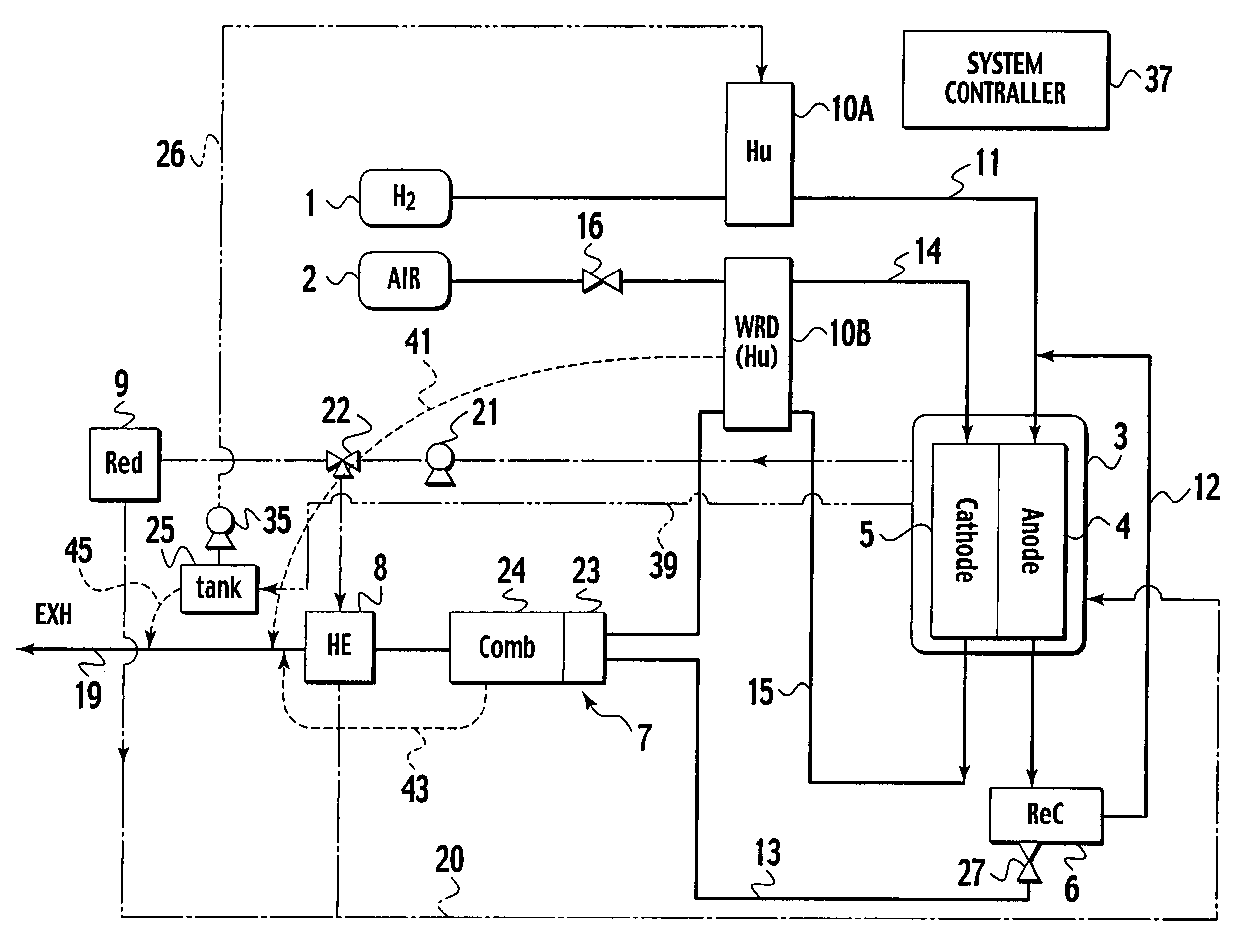
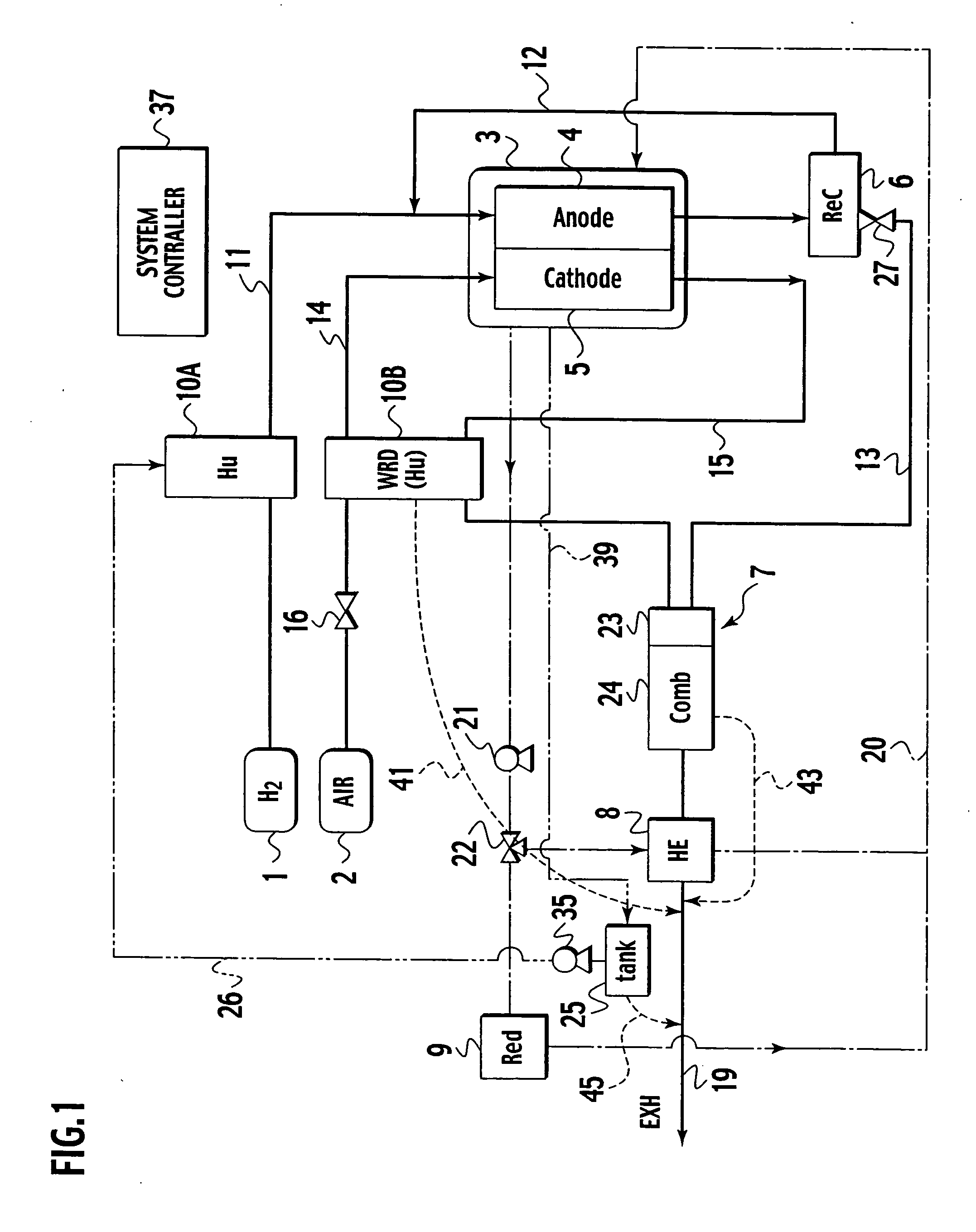
[0023] A fuel cell system according to the first embodiment will be explained with reference to FIGS. 1 to 3.
[0024] Structure of the Fuel Cell System
[0025] In FIG. 1, the fuel cell system has a hydrogen supply unit (fuel gas supply unit) 1, an air supply unit (oxidizer gas supply unit) 2, a fuel cell 3, an anode off-gas circulator 6, a combustor 7, a heat exchanger 8, a cooling unit 9, a humidifier 10A for an anode supply gas, a humidifier 10B for a cathode supply gas, an air-flow rate control valve 16, a coolant pump 21, a three-way valve 22, an anode off-gas discharge valve 27, and a system controller 37 to wholly control the fuel cell system. The hydrogen supply unit (fuel gas supply unit) 1 supplies hydrogen as a fuel gas through hydrogen supply conduit 11. The air supply unit (oxidizer gas supply unit) 2 supplies air as an oxidizer gas through air supply conduit 14. The fuel cell 3 has an anode (fuel electrode) 4 and a cathode (oxidizer electrode) 5 and generates electricity ...
second embodiment
[0051] A second embodiment will be explained with reference to FIG. 4. The second embodiment connects a drain 43 of a combustor 7 to an upstream side of an exhaust line 19. More precisely, a location 43b where the drain 43 of the combustor 7 is connected to the exhaust line 19 is upstream from a location 41b where a drain 41b of a humidifier 10B is connected to the exhaust line 19 and a location 45b where a drain 45 of a water tank 25 is connected to the exhaust line 19. This arrangement differs from that of the first embodiment.
[0052] In addition to the attributes of the fuel cell system of the first embodiment, the fuel cell system of the second embodiment achieves the attributes mentioned below.
[0053] The drain 43 of the combustor 7 is connected to an upstream side of the exhaust 19, to prevent a combustion gas from maintaining a high temperature when it is exhausted from the exhaust line 19 to the outside. Specifically, during a combustion operation of the combustor 7, the dra...
third embodiment
[0055] A third embodiment will be explained with reference to FIG. 5. The third embodiment differs from the second embodiment in that it provides a temperature sensor (temperature detector) 47 on an exhaust line 19, to detect a temperature in the exhaust line 19. The temperature sensor 47 is arranged on the exhaust line 19 at a location downstream from a location 43b where a drain 43 of a combustor 7 is connected to the exhaust line 19 and upstream from a location 41b where a drain 41 of a humidifier 10B is connected to the exhaust line 19 and a location 45b where a drain 45 of a water tank 25 is connected to the exhaust line 19.
[0056] In addition to the characteristics of the fuel cell system of the second embodiment, the fuel cell system of the third embodiment provides an characteristics of correctly measuring the temperature of a combustion gas indicative of a combustion state of the combustor 7. The temperature detected by the temperature sensor 47 is dependent on a combustion...
PUM
 Abstract
Description
Claims
Application Information