Dual-circuit modular injection tube

Active Publication Date: 2015-06-25
SAFRAN HELICOPTER ENGINES
View PDF7 Cites 17 Cited by
  • Summary
  • Abstract
  • Description
  • Claims
  • Application Information

AI Technical Summary

Benefits of technology

[0010]In order in particular to facilitate feeding the main circuit with fuel, the manifold assembly may further include a feed coupling suitable for being connected to a first source of fuel and presenting at least a first endpiece receiving one end of a transfer tube of the main circuit for feeding it with fuel from said first source. In order in particular to increase the number of injectors, while limiting the number of components in the manifold assembly, said feed coupling may also include a mounting surface with an orifice in fluid flow communication with the first endpiece of the feed

Problems solved by technology

Nevertheless, that normally requires injector manifold assemblies that are more complex, since they incorporate, in parallel with a main circuit, an auxiliary circuit for use when sta

Method used


Image

  • Dual-circuit modular injection tube
  • Dual-circuit modular injection tube
  • Dual-circuit modular injection tube

Examples


Embodiment Construction

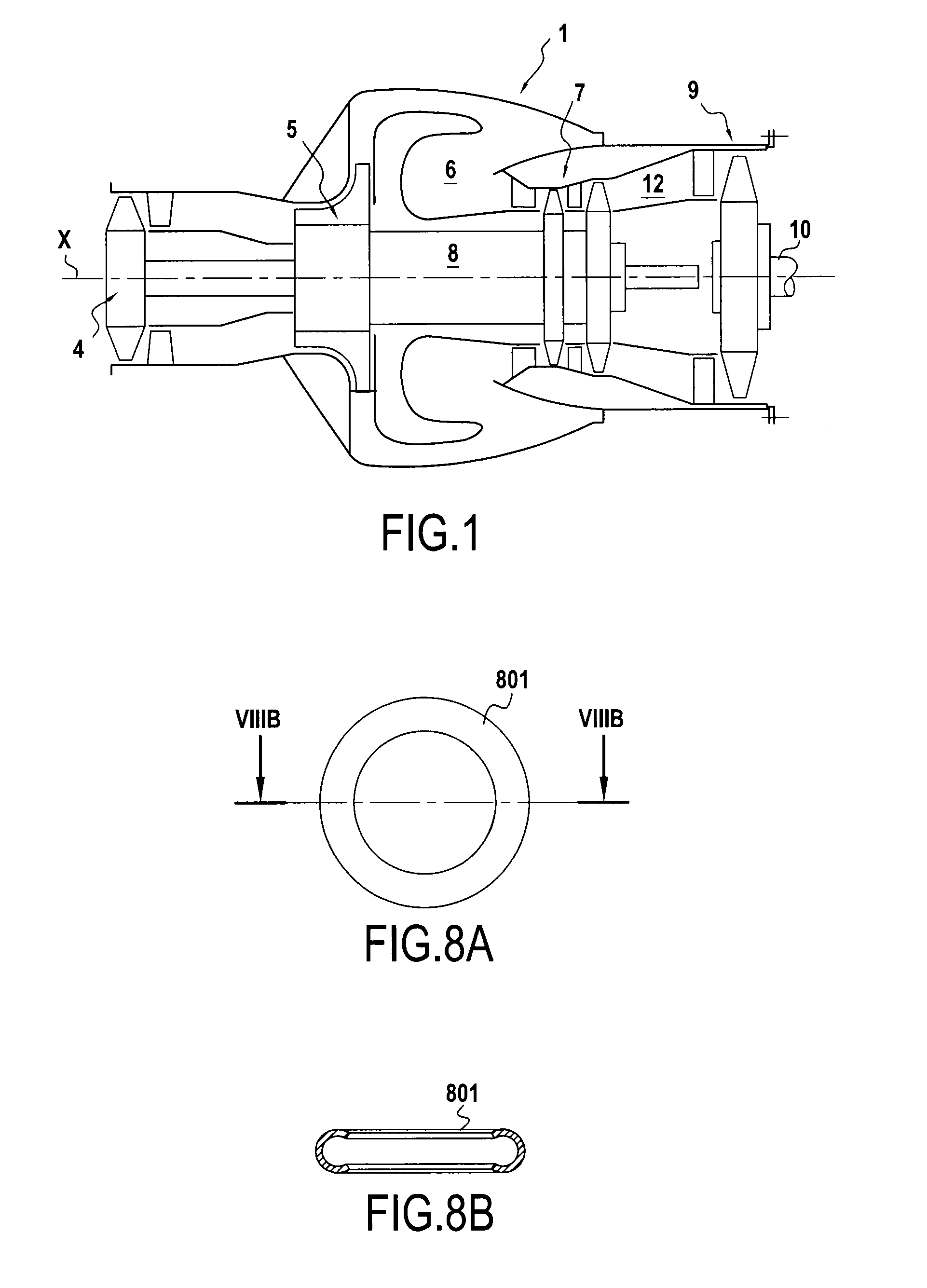
[0022]A turbomachine, and more specifically a turboshaft engine 1 is shown in FIG. 1. This engine 1 comprises an axial compressor 4, a radial compressor 5, an annular combustion chamber 6, a first combustion gas turbine 7, and a first rotary shaft 8 of central axis X for coupling together in rotation the disks of the first combustion gas turbine 7 and the compressors 4 and 5, in such a manner that rotation of the turbine serves to actuate the compressors 4 and 5 while the engine 1 is in operation. The engine 1 also has a second combustion gas turbine 9 known as a “free” turbine and a second rotary shaft 10, likewise in alignment with the central axis X, and coupling the free turbine 9 to a power outlet. Thus, rotation of the disk of the free turbine 9 while the engine 1 is in operation can serve to actuate an external device, such as a helicopter rotor, for example.

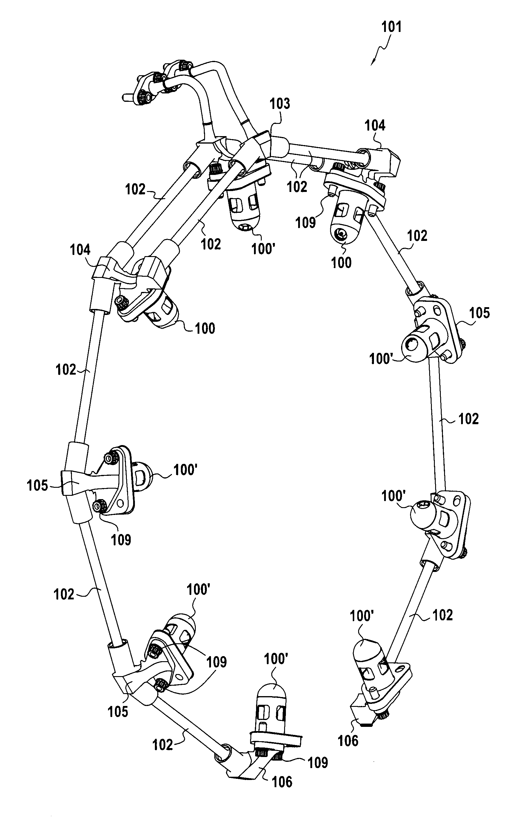
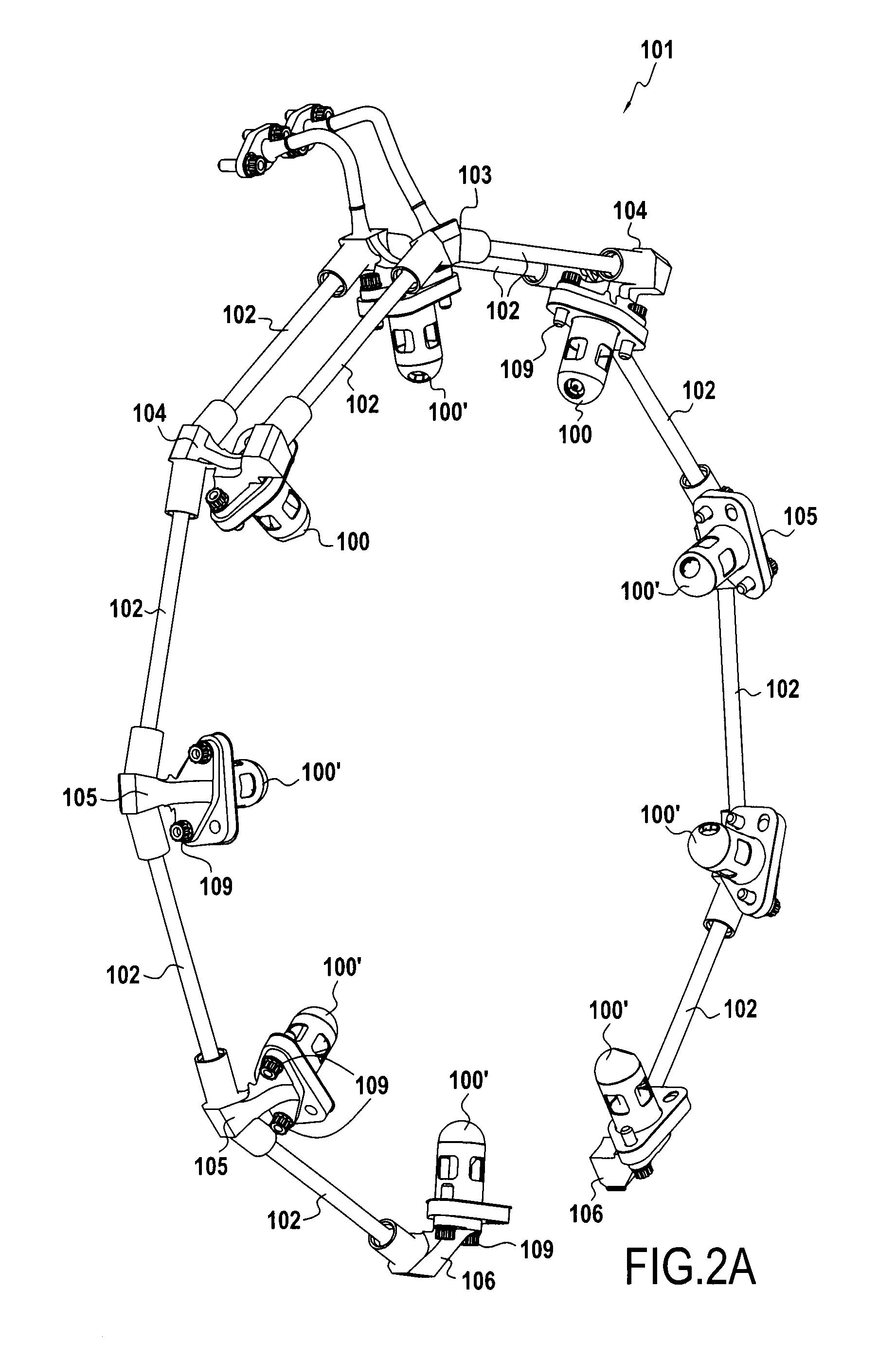
[0023]In order to inject fuel into the combustion chamber 6, the combustion chamber has a plurality of injectors 100, 1...


PUM


Abstract

A turbomachine injection manifold assembly including a main circuit for feeding fuel to sets of injectors, and an auxiliary circuit for feeding fuel to a set of injectors. The manifold assembly also includes i a double coupling presenting a first endpiece receiving one end of a transfer tube of the main circuit, a second endpiece receiving one end of a transfer tube of the auxiliary circuit, and a mounting surface with a first orifice in fluid flow communication with the first endpiece and a second orifice in fluid flow communication with the second endpiece said the mounting surface of the double coupling being suitable for connecting the double coupling to an injector of said first set of injectors.

Description

BACKGROUND OF THE INVENTION[0001]The present invention relates to the field of turbomachines and more particularly to the field of injection manifold assemblies for turbomachines.[0002]In the present context, the term “turbomachine” covers any machine in which energy can be transferred between a flow of fluid and at least one set of blades, such as for example a compressor, a pump, a turbine, or indeed a combination of at least two of these. Certain internal combustion turbomachines, such as gas turbines, turboshaft engines, turbofans or turbojets, or turboprops, enable the chemical energy of a fuel to be converted into mechanical energy by combustion of the fuel in the working fluid, with combustion taking place in a combustion chamber. Typically, such turbomachines comprise at least one compressor upstream from the combustion chamber and at least one turbine downstream from the combustion chamber and coupled to the compressor in order to actuate it by partial expansion of the work...

Claims


Application Information

Patent Timeline
IPC IPC(8): F02C7/22
CPCF05D2220/32F02C7/222F02C7/228F02C9/26F05D2270/31F02C7/22F23R3/28F23R3/36
Inventor ZORDAN, CEDRIC ROGERFRANCEZ, XAVIER
Owner SAFRAN HELICOPTER ENGINES
Why Eureka
Try Eureka