

Projection display apparatus
- Summary
- Abstract
- Description
- Claims
- Application Information
AI Technical Summary
Benefits of technology
Problems solved by technology
Method used
Image

Examples
Embodiment Construction
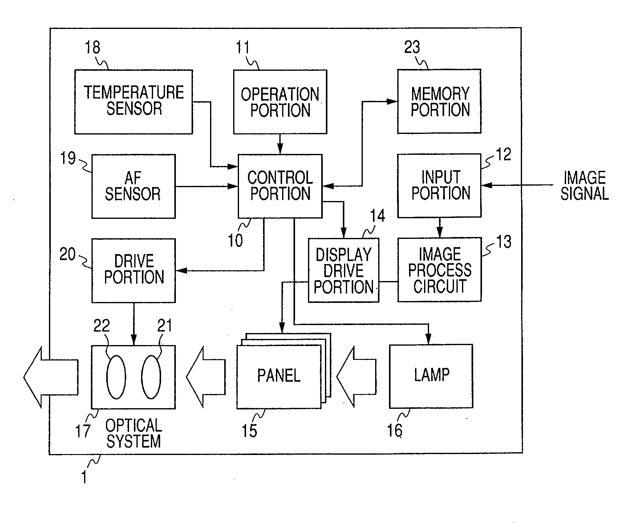
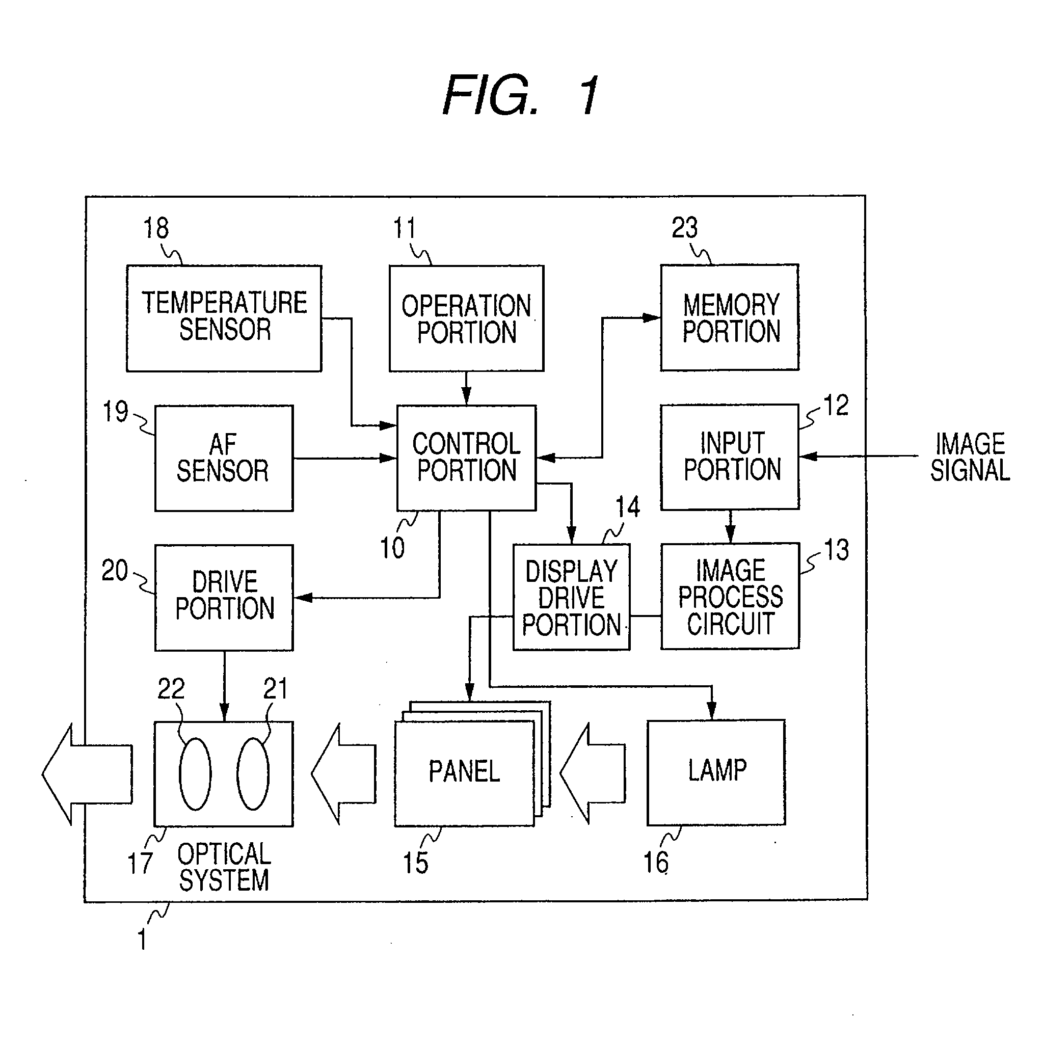
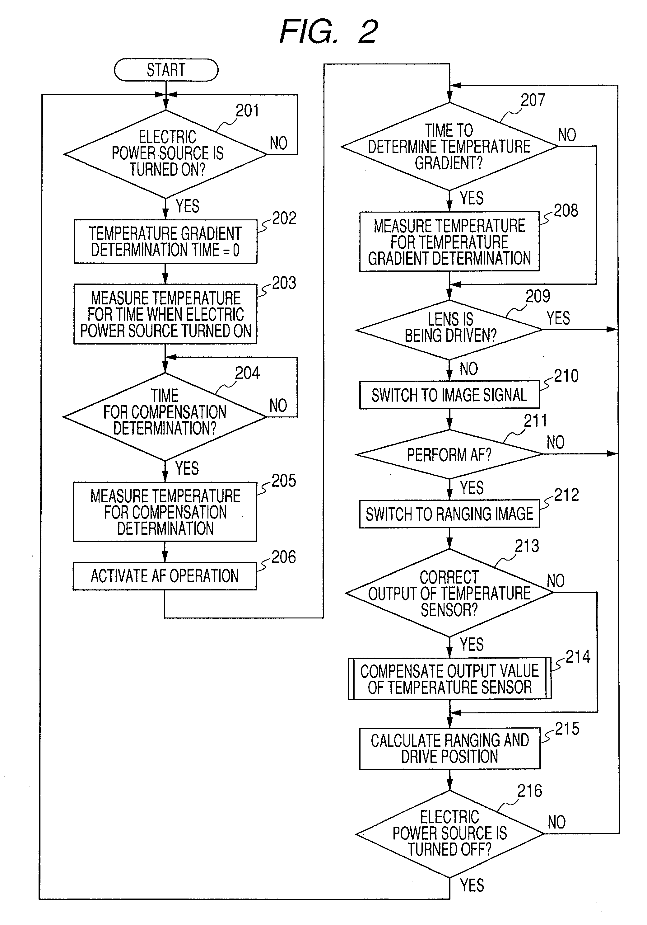
[0016]In the following, an embodiment of the present invention will be described with reference to the accompanying drawings. FIG. 1 shows the configuration of a liquid crystal projector (projection display apparatus). FIG. 1 illustrates a liquid crystal projector 1 which includes a control portion (control unit) 10, an operation portion 11, an input portion 12, an image processing circuit 13, a display drive portion 14, a liquid crystal panel (display unit) 15, a light source lamp 16, a projection lens system 17, a temperature sensor 18, an AF sensor (focus sensor) 19, a drive portion (drive unit) 20 and a memory portion (memory unit) 23. The control portion 10 is electrically connected with the operation portion 11, the display drive portion 14, the temperature sensor 18, the AF sensor 19, the drive portion 20 and the memory portion 23.
[0017]The operation potion 11 has a power switch for turning on / off the power and an AF switch for activating the AF operation. An image signal is ...
PUM
 Abstract
Description
Claims
Application Information