System and method for power control in a LED luminaire

a technology of led luminaires and power control, applied in the direction of electric variable regulation, outdoor lighting, lighting heating/cooling arrangements, etc., can solve the problems of reducing the feasibility of leds as viable lighting sources, limiting the wide spread adoption of leds as commercial and residential lighting sources, and bulky ac to dc converters

Inactive Publication Date: 2007-08-23
REMCO SOLID STATE LIGHTING
View PDF2 Cites 189 Cited by
  • Summary
  • Abstract
  • Description
  • Claims
  • Application Information

AI Technical Summary

Benefits of technology

[0006] The present invention in one aspect is directed to an LED luminaire comprising an interface for connecting the luminaire to a source of electrical power, an LED array producing a light of a suitable intensity and color for the task for which the luminaire is to be used, a power control section for supplying and controlling power to the LED array and a light diffuser for diffusing the light from the LED array to produce suitable light for the task for which the luminaire is to be used.

Problems solved by technology

The AC to DC converters are bulky, making it a challenge to fabricate a LED lighting fixture to replace, for example, an existing Edison type incandescent light bulb fixture.
Furthermore, the optical performance of LED's are affected by a rise in temperature This thermal problem has reduced the feasibility of LEDs as viable lighting sources and has limited the wide spread adoption of LEDs as commercial and residential lighting sources.

Method used


Image

  • System and method for power control in a LED luminaire
  • System and method for power control in a LED luminaire
  • System and method for power control in a LED luminaire

Examples


first embodiment

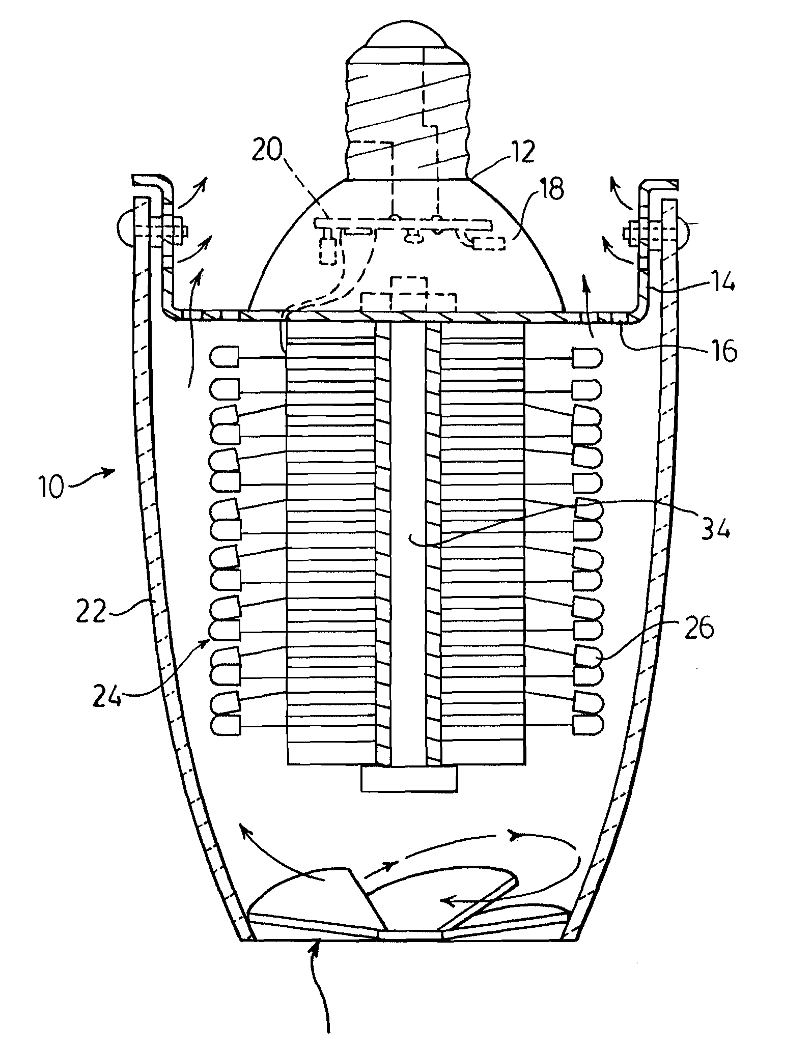
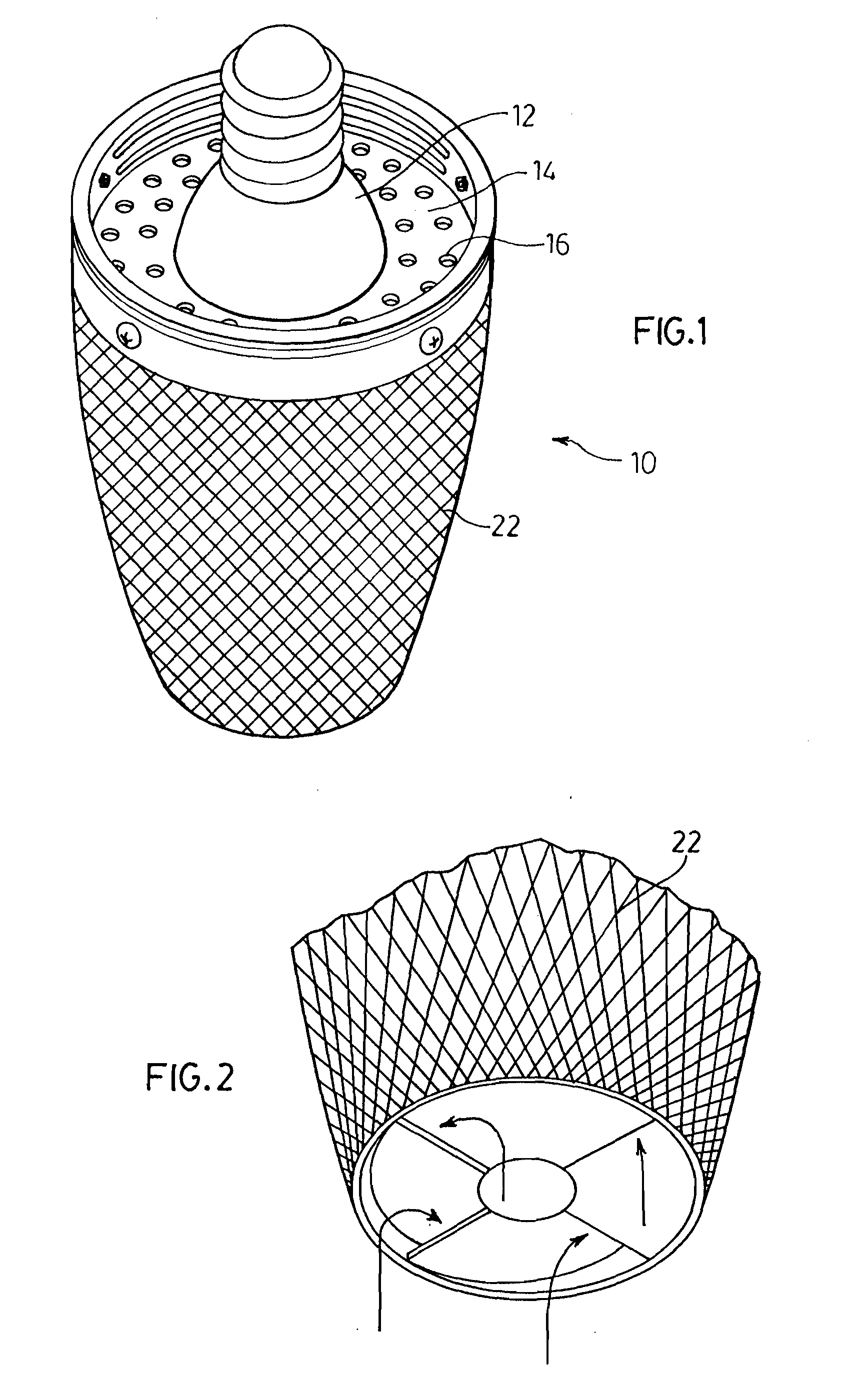
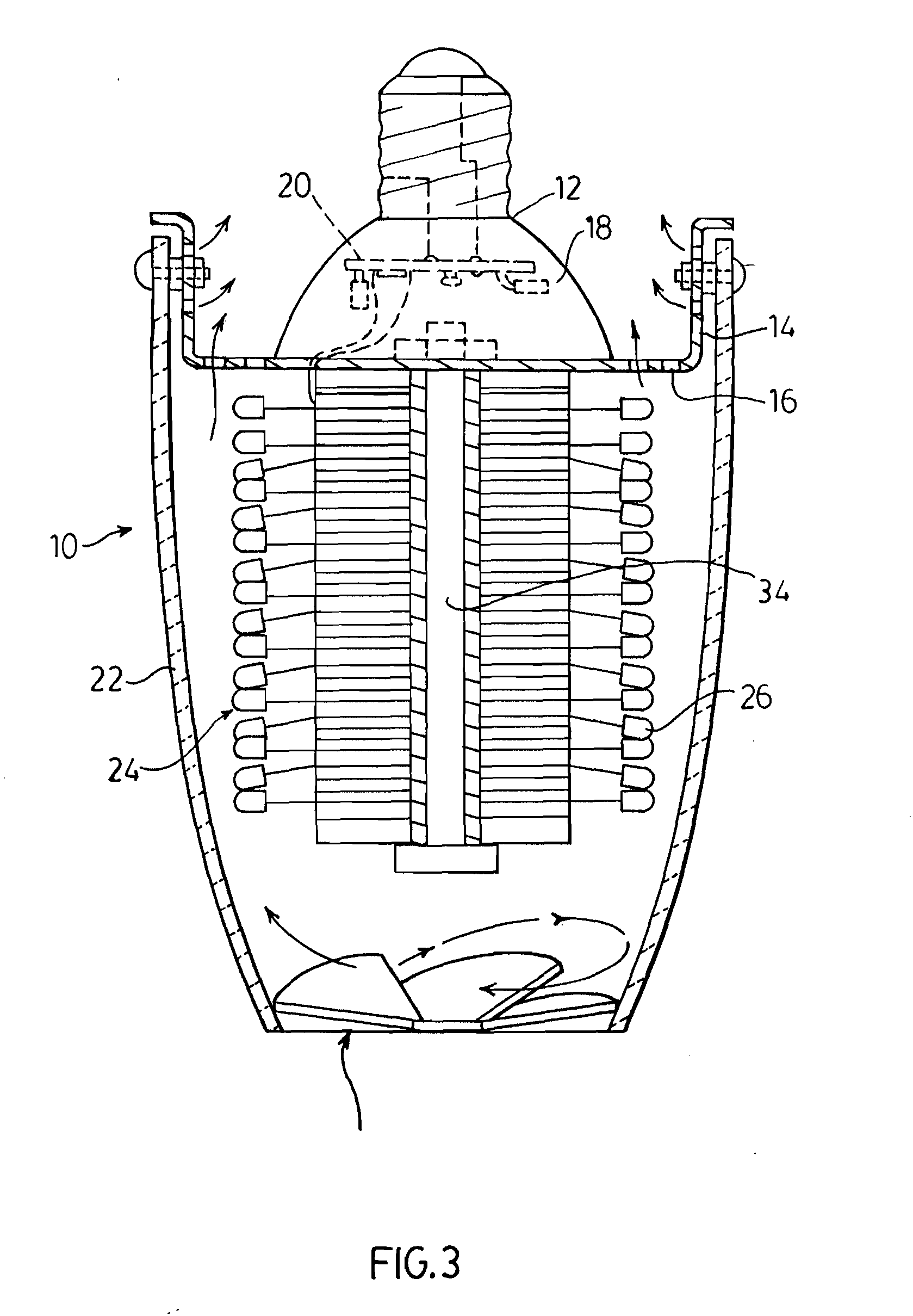
[0055] an LED luminaire of the present invention for use as a replacement for residential incandescent light bulbs is illustrated in FIGS. 1 to 5 and generally indicated by the numeral 10. The LED luminaire 10 is provided with a screw base interface 12, which fits into the standard screw base fixtures. The screw base 12 is affixed to a thermal cap 14 for enclosing the LEDs and containing openings 16 to allow for air flow through the luminaire 10 as will be described later.

[0056] The screw base 12 also houses the power control electronics used for powering the LED array. The screw base 12 is a flanged form with a cavity space 18 that accommodates the power control circuitry 20. An acrylic frosted diffused lens 22 covers the LED array 24 and is attached to the thermal cap 14.

[0057] The electrothermal core section 24 makes possible the interconnection of a very high-density array of LEDs 26. The core 24 provides electrical interconnection, thermal collection and physical support for t...

third embodiment

[0070] the LED luminaire of the present invention for use in replacement of fluorescent light fixtures as illustrated in FIGS. 9 to 14 generally indicated by the numeral 110. The LED luminaire 110 illustrated in the figures is adapted to be suspended from a ceiling 112. A mounting bracket 114 such as that illustrated in the figures is attached to the ceiling 112 over the electrical outlet box 116. The luminaire 110 is suspended from the bracket 114 through the use of suitable suspension guy wires 118 and is connected to the electrical box 116 by wire 120. Wire 120 is in turn connected to a control box 122 which contains the power control circuitry for supplying and controlling the power to the LED array assembly 124, the details of which will be described further below. The light from the LED array 124 passes through a diffuser system 126 to provide for even and uniform light output from the luminaire. The details of the light components of this embodiment are illustrated in detail ...

fourth embodiment

[0075] a LED luminaire of the present invention is illustrated in FIG. 15 generally indicated by the numeral 200. This luminaire is provided with an LED array 212 mounted within a housing 214. A diffuser 216 is provided to attach to the housing 214 and hold the components within the housing 214. In order to space the LED array 212 from the diffuser 216, a spacer strip 218 is provided which allows for airflow for cooling of the LED array 212. The LED's are powered by a powercontrol component 220 connected to an electrical source by wire 222. The embodiment of the invention illustrated in FIG. 15 is particularly useful for strip lighting or replacing fixtures having a single fluorescent tube.

[0076] This embodiment of the LED luminaire of the present invention is of particular use for grow bulbs for use in greenhouses and other such applications. These grow bulbs provide for photosynthetic active radiation (PAR) which typically is light in the wave length range 400 to 525 nm, 610 to 72...


PUM


Abstract

The present invention is directed to an LED lighting source comprising a housing adapted for coupling to an AC power source; a rectifier circuit for converting the AC power to a DC supply; a power control circuit disposed in the housing and electrically connected to the DC supply; a string of LED's electrically connected between a control node of the power control circuit and the DC supply, the LEDs in the string being connected in series and being of a number selected to produce a voltage difference across the power control circuit sufficient to power active components of said power control circuit when powered from the DC supply and the power control circuit for limiting a forward current through the string to a nominal forward current of a single LED.

Description

CROSS REFERENCE TO RELATED APPLICATIONS [0001] This is a continuation-in-part of International Patent application Serial No. PCT / CA2005 / 001255, filed Aug. 18, 2005, which is a continuation-in-part of U.S. Provisional application Ser. No. 60 / 602,335 filed Aug. 18, 2004.FIELD OF THE INVENTION [0002] The present invention relates to a LED (light emitting diode) luminaire. In particular, the present invention relates to a system and method for power regulation of an LED array in high lumen output residential and commercial applications. BACKGROUND OF THE INVENTION [0003] It is recognised that LED light sources are theoretically more efficient than incandescent light bulbs and solutions have been proposed to construct LED luminaires as for example taught in U.S. Pat. No. 6,609,804. A luminaire usually refers to a complete lighting unit which contains one or more electric lighting sources and associated reflectors, refractors, housing, and such support for those items as necessary with th...

Claims


Application Information

Patent Timeline
Patent Type & Authority Applications(United States)
IPC IPC(8): F21V11/00
CPCF21S8/06F21V29/83F21V3/02F21V29/004F21Y2101/02F21Y2111/008F21V29/20F21S8/026F21K9/135F21W2131/103Y10S362/80F21V29/506F21V29/75F21V29/763F21S8/086F21K9/232F21Y2115/10F21Y2107/60F21V29/74
Inventor RUSSELL, RONALD JAMES
Owner REMCO SOLID STATE LIGHTING
Why Eureka
Try Eureka