

Method and apparatus for converting direct current to alternating current
a direct current and alternating current technology, applied in the field of micro-inverters, can solve the problems of reducing the cost of electricity from the grid, reducing the efficiency of the grid, and increasing the cost of electricity generation
- Summary
- Abstract
- Description
- Claims
- Application Information
AI Technical Summary
Problems solved by technology
Method used
Image

Examples
Embodiment Construction
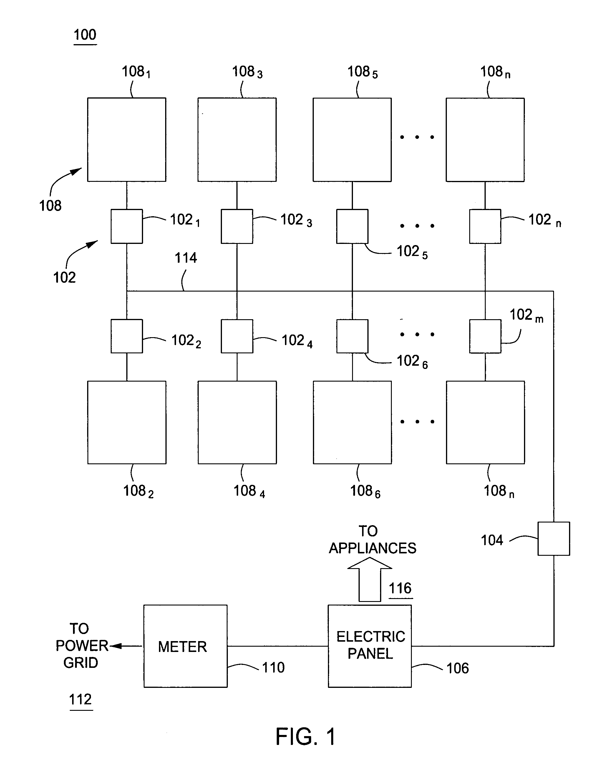
[0019]FIG. 1 is a block diagram of an exemplary power generation system 100 that utilizes one embodiment of the present invention. This diagram only portrays one variation of the myriad of possible system configurations. The present invention can function in a variety of environments and systems.
[0020]The power generation system 100 comprises a plurality of micro-inverters 1021, 1022 . . . 102n, a junction box 104, an electric panel 106, a plurality of photovoltaic panels 1081, 1082 . . . 108n, and an electric meter 110. The system 100 supplies power to a power grid 112, appliances 116, or both. The plurality of photovoltaic panels 1081, 1082 . . . 108n are well known in the art and are used for generating DC power from solar energy. The plurality of photovoltaic panels 1081, 1082 . . . 108n (also referred to herein as solar panels) may be of any size or shape. Even though the system 100 shows eight (8) photovoltaic panels 1081, 1082 . . . 108n, the system 100 may include any number...
PUM
 Abstract
Description
Claims
Application Information