Endplay measurement tool and method

a technology of endplay and measurement tool, which is applied in the direction of mechanical measuring arrangement, manufacturing tools, instruments, etc., can solve the problems of inconvenient and efficient way of measuring endplay, difficult installation, use and removal of endplay, and time-consuming. achieve the effect of improving accuracy and repeatability, and convenient and efficient way

a technology of endplay and measurement tool, which is applied in the direction of mechanical measuring arrangement, manufacturing tools, instruments, etc., can solve the problems of inconvenient and efficient way of measuring endplay, difficult installation, use and removal of endplay, and time-consuming. achieve the effect of improving accuracy and repeatability, and convenient and efficient way

US20070294900A1Active Publication Date: 2007-12-27INT TRUCK INTPROP LLC

Image

  • Endplay measurement tool and method
  • Endplay measurement tool and method
  • Endplay measurement tool and method

Examples


Embodiment Construction

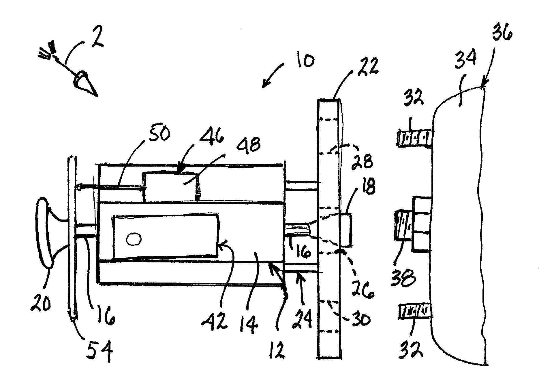
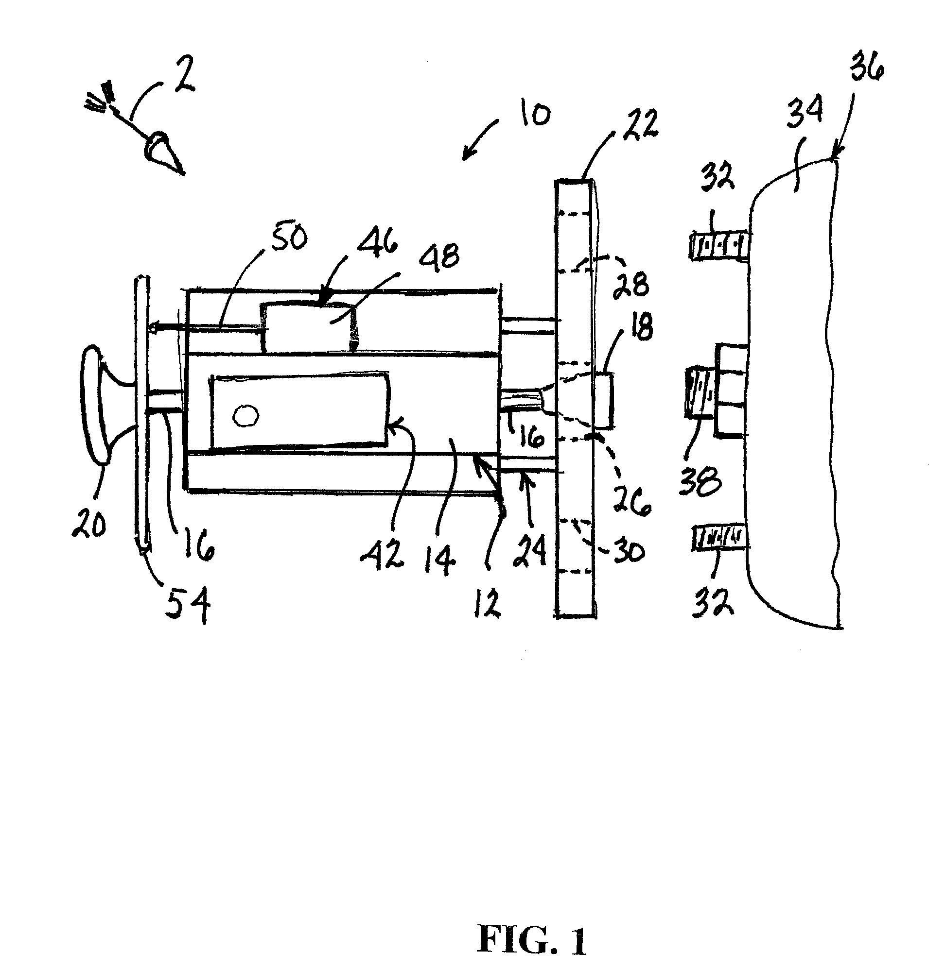
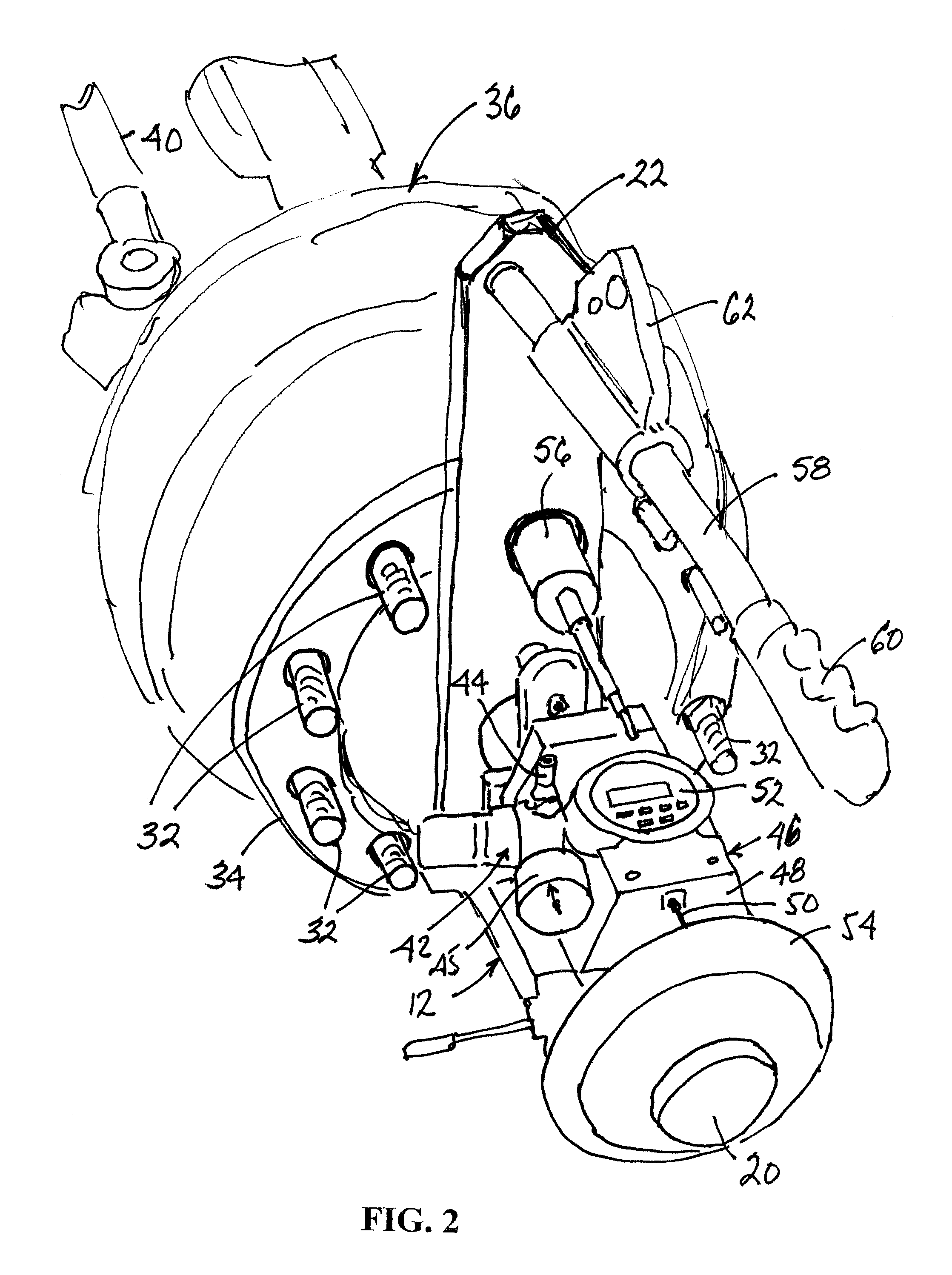
[0033]FIGS. 1 and 2 show tool 10 to comprise a pneumatic cylinder 12 having a cylinder housing 14 and a though-shaft, or through-rod, 16 running completely through housing 14 so as to protrude from opposite ends of the housing. An internally threaded socket 18 is attached to one axial end of rod 16 and a tightening / untightening handle, or knob, 20 is attached to the other end.

[0034] A mounting plate 22 is supported on housing 14 and is disposed at the same axial end of the housing as the end of rod 16 to which socket 18 is attached. Mounting plate 22 adapts cylinder 12 for mounting on an axle hub and is attached to the exterior of housing 14 through a mounting structure 24 that places mounting plate 22 a short distance frontally of the housing.

[0035] Mounting plate 22 has a generally rectangular shape that gives the mounting plate the appearance of a long, generally flat bar as perhaps better seen in FIG. 2. Mounting plate 22 comprises several through-holes running in the directio...


PUM

PropertyMeasurementUnit
mechanical advantageaaaaaaaaaa
diameteraaaaaaaaaa
external forceaaaaaaaaaa

Abstract

A tool (10) and method for measuring endplay between an axle shaft (36) and an axle hub (34) of an axle assembly. A mounting plate (22) is fastened to the hub, and one end of a through-rod (16) whose ends protrude from opposite ends of a housing (14) of a fluid-operated device (12) is fastened to the axle shaft by applying an external force to the other end of the through-rod while fluid is not operating the fluid-operated device. With the mounting adapter and the through-rod secured as described, fluid is delivered to the fluid-operated device to move the through-rod relative to the housing, and the resulting relative movement between the through-rod and the housing is measured by a measuring device (48).

Description

FIELD OF THE INVENTION [0001] This invention relates to a tool and method for measuring endplay between parts in an assembly. More particularly, the invention relates to a tool and method for measuring axial endplay between a hub and shaft that are on an end of an axle assembly for a motor vehicle such as a large truck. BACKGROUND OF THE INVENTION [0002] A typical large truck comprises axle assemblies on which wheels are mounted. At its opposite ends, a typical front axle assembly comprises steerable shafts, or spindles, and hubs journaled for rotation on the shafts, or spindles. The hubs have circular patterns of outwardly protruding screw studs, or lugs, that match circular bolt hole patterns in the hubs of the wheels to allow the wheels to be placed onto the axle hubs with the lugs on the axle hubs protruding through the holes of the bolt hole patterns in the wheel hubs. Lug nuts are then threaded onto ends of the lugs and tightened to force the wheel hubs against the faces of th...

Claims


Application Information

Patent Timeline
27 Dec 2007
Publication
US20070294900A1
IPC
G01B5/24
CPC
Y10T29/53922; G01B5/14
Inventors
SMITH, RAND D.; REYNOLDS, THOMAS